


Precision CNC Machining for Sensors: Materials, Tolerances, and What to Expect
Precision CNC machining for sensors produces tight-tolerance housings, probe bodies, and mounting brackets from materials like Aluminum 6061-T6, 316L stainless steel, and PEEK. Typical tolerances range from ±0.005mm to ±0.02mm. It's the most reliable process for low-to-mid volume sensor components where dimensional accuracy directly affects performance.
What Is Precision CNC Machining for Sensors?

Precision CNC machining for sensors means cutting metal or plastic parts to extremely tight tolerances so they work correctly inside a sensor assembly. A bore that's 0.02mm off-center misaligns the piezoelectric element. A sealing face that's too rough lets fluid bypass the gasket. In sensor manufacturing, dimensional accuracy isn't a quality preference. It's a functional requirement.
CNC machining handles this better than any other process at low-to-mid volumes. 5-axis milling centers like the DMG Mori DMU 50 can hold ±0.005mm on critical features, which casting and 3D printing can't match without expensive secondary operations.
At GD Prototyping, we machine sensor components for clients in industrial automation, medical devices, and automotive testing. You can see real examples of these parts in our CNC machining case library.
Which Sensor Components Are CNC Machined?
Most precision sensor assemblies include at least one CNC-machined part. The most common components we produce include:
- Sensor housings — Enclosures that protect the sensing element, with bores, threaded ports, and sealing grooves
- Probe bodies — Long, slim cylindrical parts that require concentricity within 0.01mm TIR
- Mounting brackets — Structural parts that hold the sensor at a precise angle or position
- End caps and connectors — Sealing parts that must mate flat to Ra 0.8 µm or better
- Encoder rings and targets — Precision-profiled parts for rotational or linear position sensors
Each of these parts has at least one feature where dimensional error directly causes sensor failure. That's why they're machined, not cast or printed.
Best Materials for Precision Sensor Parts
Material choice depends on the sensor's operating environment. Here are the most common options:
| Material | Typical Use | Key Property | Machinability |
|---|---|---|---|
| Aluminum 6061-T6 | Pressure, flow, temperature sensors | Lightweight, corrosion-resistant | Excellent |
| 316L Stainless Steel | Chemical, marine, food-grade sensors | High corrosion resistance | Good |
| Titanium Grade 5 (Ti-6Al-4V) | Aerospace, high-vibration sensors | High strength-to-weight | Moderate |
| PEEK Plastic | Medical, electrical isolation sensors | Chemical resistance, low weight | Good |
| Brass C360 | Low-pressure fluid sensors | Easy threading, good sealing | Excellent |
Aluminum 6061-T6 is the most common starting point. It meets ASTM B209 standards, machines at high speeds with carbide tooling, and accepts anodizing for corrosion protection. For harsher environments, 316L stainless steel per ASTM A276 is the standard upgrade.
If you're unsure which material fits your sensor application, our engineering team reviews your requirements before quoting. Browse our full CNC machining capabilities to see what we work with.
What Tolerances Can CNC Machining Hold on Sensor Parts?
Tolerances depend on the feature type, material, and machine setup. Here's a practical reference:
| Feature | Achievable Tolerance | Notes |
|---|---|---|
| General dimensions | ±0.05mm | Standard CNC output |
| Critical bores | ±0.005mm to ±0.01mm | Requires 5-axis + boring bar |
| Sealing face flatness | 0.005mm | Finish pass required |
| Surface roughness | Ra 0.4 to Ra 1.6 µm | Depends on finish strategy |
| Thread accuracy | 6H/6g fit | Go/No-Go gauged |
| Concentricity | 0.008mm TIR | Spring pass + CMM verified |
Most sensor housing projects fall in the ±0.01mm to ±0.02mm range for critical features. Tighter than ±0.005mm is possible but requires controlled temperature environments and extended cycle times, which affects cost and lead time.
CNC Machining vs. Other Processes for Sensor Parts
Engineers often ask whether investment casting or metal 3D printing can replace CNC machining for sensor components. Here's an honest comparison:
| Process | Typical Tolerance | Surface Finish (as-processed) | Min Volume | Best For |
|---|---|---|---|---|
| CNC Machining | ±0.005mm to ±0.05mm | Ra 0.4 to Ra 3.2 µm | 1 unit | Prototypes to 5,000 units |
| Investment Casting | ±0.1mm to ±0.3mm | Ra 3.2 to Ra 6.3 µm | 500+ units | High volume, simple shapes |
| Metal 3D Printing (DMLS) | ±0.1mm to ±0.2mm | Ra 6 to Ra 12 µm as-printed | 1 unit | Complex internal geometry |
| Injection Molding (plastic) | ±0.05mm to ±0.2mm | Ra 0.8 to Ra 1.6 µm | 1,000+ units | High-volume plastic parts |
For sensor components under 5,000 units with tolerances tighter than ±0.05mm, CNC machining wins on accuracy, lead time, and total cost. Casting only becomes competitive above 1,000+ identical units where tooling cost is amortized.
What Does the CNC Machining Process Look Like for Sensor Parts?
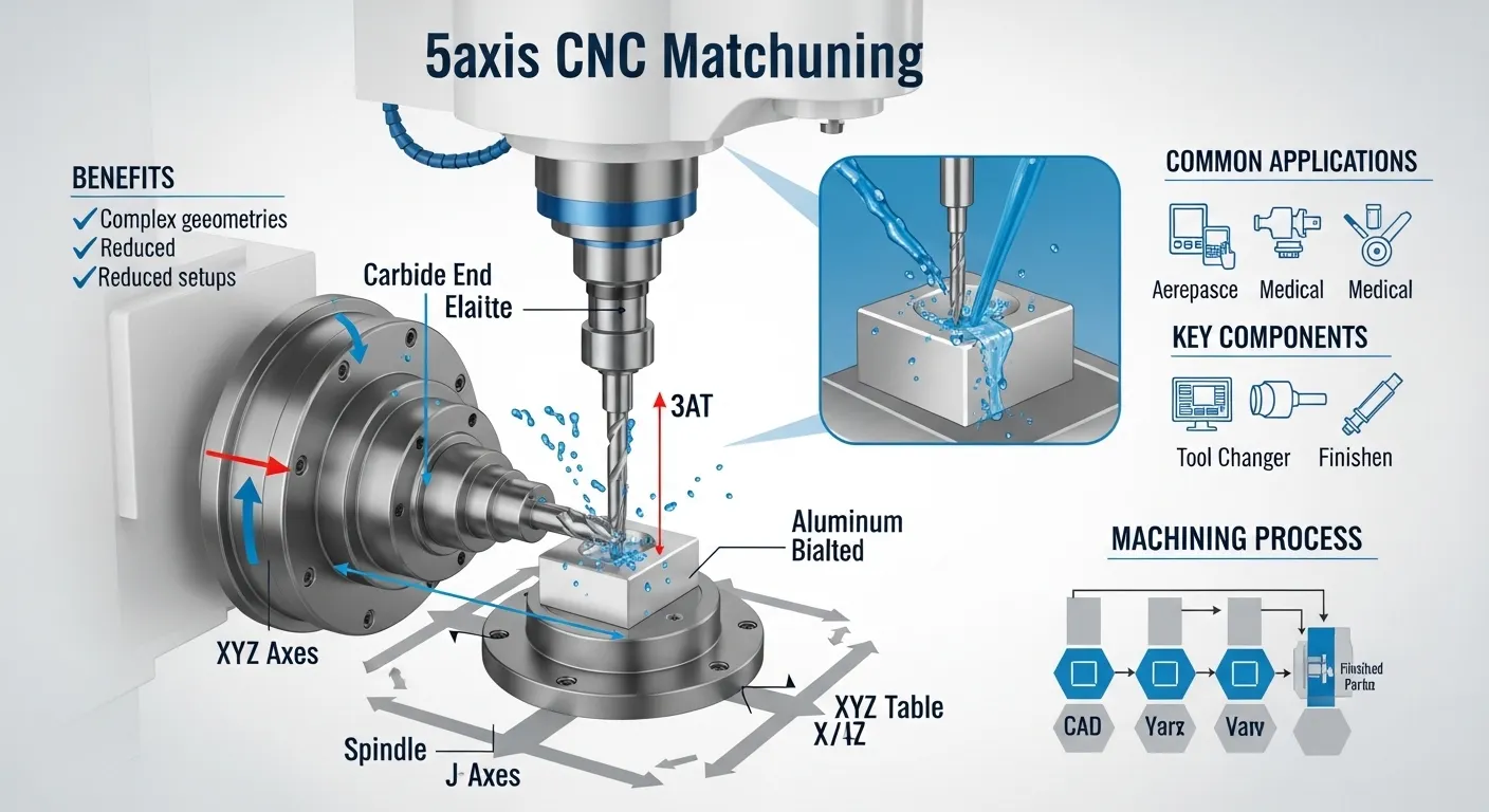
Here's a typical workflow for a sensor housing order at GD Prototyping:
- DFM Review — Our engineers check your STEP or IGES file for features that risk tolerance failure before cutting starts
- CAM Programming — Toolpaths designed in Mastercam with separate roughing and finishing strategies for thin-wall and deep-bore features
- Fixture Design — Custom soft-jaw or vacuum fixtures to prevent clamping distortion on thin-wall sections
- Roughing — 70 to 80% of billet material removed at high feed rates, leaving 0.2 to 0.3mm stock on critical surfaces
- Finishing — Slow, controlled passes with small-diameter carbide tooling to hit final dimensions and surface finish
- In-process Gauging — Plug gauges and profilometers used every 10 to 25 parts during production runs
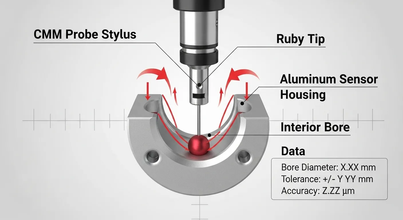
- CMM Inspection — Final parts measured on a Zeiss Contura CMM with full GD&T report
- Delivery Documentation — Material cert, CMM report, and Certificate of Conformance shipped with parts
This process consistently delivers first-pass yields above 99% on sensor housing projects. See real project outcomes in our CNC machining case studies.
Industries That Use Precision CNC Machined Sensor Parts
Sensor components machined to tight tolerances appear across many industries:
- Industrial automation — Pressure sensors, flow meters, proximity sensors in process control systems
- Automotive — ABS wheel speed sensors, throttle position sensors, crash detection housings
- Medical devices — Implantable pressure monitors, diagnostic probe bodies, fluid flow sensors
- Aerospace — Altitude sensors, fuel pressure housings, vibration sensor mounts
- Oil and gas — Downhole pressure sensors in 316L stainless or Inconel
Each industry has its own material and documentation standard. Automotive sensor parts often follow IATF 16949. Medical parts require traceability under ISO 13485. At GD Prototyping, we work with the documentation requirements your industry demands.
How to Get a Quote for Precision Sensor Machining
Getting a quote is straightforward. You'll need:
- 3D CAD file in STEP, IGES, or STP format
- 2D drawing with all critical dimensions, tolerances, and surface finish callouts
- Material specification — grade and condition (e.g., Aluminum 6061-T6, ASTM B209)
- Quantity and required lead time
- Quality documentation requirements (CMM report, material cert, CoC)
You don't need a perfect drawing to start. If you have a CAD file and a rough spec, our engineers will review it and flag any issues before pricing.
Request a quote at GD Prototyping and get a response within 12 hours.
FAQ
What's the minimum wall thickness CNC machining can hold on a sensor housing?
For Aluminum 6061-T6, we regularly machine walls down to 0.8mm with custom fixturing and reduced cutting parameters. Stainless steel walls can go down to 1.0mm reliably. Thinner than 0.8mm requires case-by-case DFM review because thermal and clamping forces become significant variables.
How long does it take to machine sensor housings?
Prototypes (1 to 5 parts) typically take 3 to 5 working days after DFM review. Production runs of 50 to 200 units take 10 to 14 working days. Rush services for simple geometries are available in 5 to 7 days. Lead time depends on part complexity, material availability, and inspection requirements.
Can you machine sensor parts from customer-supplied raw material?
Yes. We accept customer-supplied billet or bar stock. All supplied material must include a mill certificate. We verify material compliance before machining begins. This is common for aerospace and medical clients with certified supply chains.
What file formats do you accept for CNC sensor part orders?
We work with STEP (.stp, .step), IGES (.igs), STP, and DXF files for 2D drawings. PDF drawings are accepted as a reference alongside 3D CAD. Mastercam and SolidWorks native files are also compatible with our CAM software.
Do you offer surface finishing for sensor housings after machining?
Yes. We offer anodizing (Type II and Type III hard anodize) for aluminum parts, electropolishing for stainless steel, and black oxide coating. Surface treatment is quoted separately and adds 3 to 5 working days to the lead time.
Conclusion
Precision CNC machining for sensors is the go-to process when tolerances are tighter than ±0.05mm, volumes are under 5,000 units, and performance depends on dimensional accuracy. Choosing the right material, fixture strategy, and inspection process makes the difference between a batch that passes and one that doesn't.
GD Prototyping machines sensor components for clients across automation, automotive, and medical sectors. If you have a sensor part that needs ±0.01mm tolerances, we're ready to review your files.
Get a free quote now — response within 12 hours.
