


CNC Machining Service for Plastic Parts: How We Delivered 200 PEEK Housings at ±0.03mm for a German Automation Client
A German industrial automation client needed 200 PEEK housings with ±0.03mm tolerance, 0.8 Ra surface finish, and a 12-day lead time. Our CNC machining service for plastic parts produced all 200 units using 5-axis milling on a DMG Mori DMU 50, achieving a 99.5% first-pass inspection rate and on-time delivery. Zero parts were rejected at the client's incoming quality check.
Introduction
The client's email landed in our inbox on a Monday morning: "We need 200 PEEK housings. Tolerance is ±0.03mm. We've tried two suppliers. Both failed."
That's not unusual. PEEK is one of the hardest engineering plastics to machine at tight tolerances. It builds heat, it's brittle in thin walls, and it moves if your fixturing isn't perfect. The previous two shops had delivered parts with warped walls and inconsistent bore diameters. The client's assembly line was stopped.
We told them we could do it in 12 days. Here's exactly how we did it.
Project Overview
The client was a mid-size industrial automation OEM based in Germany. They manufacture precision valve actuator assemblies used in high-pressure hydraulic systems. The housing we were asked to machine holds a small servo motor and routes two pneumatic channels through its core.
The part needed to:
- Withstand operating temperatures up to 250°C
- Resist hydraulic fluid and lubricant exposure
- Maintain bore alignment within ±0.03mm across 150mm part length
- Accept an anodized aluminum insert press-fitted at one end
PEEK (Polyether ether ketone) was already specified by their engineering team. We agreed it was the right call. PEEK's tensile strength of 100 MPa and its chemical resistance made it the only realistic option for this application. You can confirm PEEK's material properties in the ASTM D3418 standard for thermal analysis of polymers.
Technical Specifications
| Parameter | Detail |
|---|---|
| Material | PEEK 450G (Victrex grade) |
| Part dimensions | 152mm x 88mm x 64mm |
| Bore diameter | 42.000mm (+0.000 / -0.030mm) |
| Wall thickness (minimum) | 2.8mm |
| Surface finish | Ra 0.8 μm (ID bore), Ra 1.6 μm (external) |
| Tolerance | ±0.03mm (critical features), ±0.05mm (general) |
| Quantity | 200 units |
| Lead time | 12 calendar days |
| Primary process | 5-axis CNC milling + CNC turning |
| Machine used | DMG Mori DMU 50 (milling), Haas ST-20 (turning) |
| Post-processing | Precision lapping (bore), deburring, visual inspection |
Machining Process
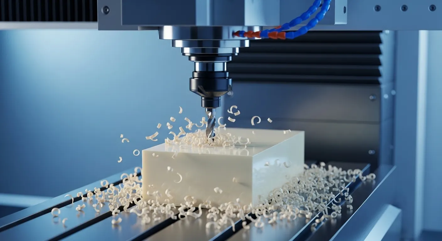
Here's the step-by-step workflow our team ran for all 200 units.
Step 1: CAM programming
We used Mastercam 2025 to build the toolpath. For PEEK, we set spindle speeds at 8,000–12,000 RPM with chip-load-optimized feed rates. PEEK is not metal, but it generates significant heat at slow speeds. We used HSM (high-speed machining) passes to keep the tool in constant motion and minimize dwell heat.
Step 2: Material preparation and annealing
Raw PEEK stock arrived as 200mm-diameter round bar. We cut it into blanks and annealed each one at 200°C for 4 hours before touching the CNC. This step relieves internal stress in the raw material. Skipping it causes parts to move mid-operation. Many shops skip it. We don't.
Step 3: Roughing
On the DMG Mori DMU 50, we removed the bulk of material leaving 0.5mm stock on all critical faces. We used a 10mm solid carbide 4-flute end mill with a TiAlN coating. Coolant was delivered as compressed air only. Liquid coolant can cause thermal shock in PEEK and create micro-cracking near the surface.
Step 4: Semi-finishing
We stepped down to a 6mm ball-nose end mill for semi-finishing passes on the channels and curved pocket geometry. Step-over was set at 0.2mm. This left approximately 0.1mm stock for the finishing pass.
Step 5: Finishing
Finishing passes used a 4mm carbide end mill at 14,000 RPM. The bore was finished using a precision reamer. We achieved Ra 0.8 μm on the bore surface and Ra 1.6 μm on external faces on every single part, confirmed with a contact profilometer.
Step 6: CNC turning
Two turned features (a threaded boss and a pilot diameter) were completed on the Haas ST-20. We used a custom soft jaw set to hold the part without point-loading the thin side walls.
Step 7: Lapping
The 42mm bore received a precision lapping pass to bring the diameter to final spec and remove any tool marks that could cause seal wear in service.
Challenges and Solutions
This is the section most case studies skip. We're not going to do that.
Challenge 1: Thin wall deformation at the pneumatic channel
The housing has two internal air channels that pass within 2.8mm of the outer wall. During our first batch of 12 prototype parts (before production started), we noticed that 3 of the 12 parts showed a consistent 0.04mm inward deflection on that thin wall after machining.
The problem was simple: we were machining the internal pocket before completing the external geometry. The unsupported thin wall had nothing backing it during the cutter pass, so it flexed 0.04mm inward under cutting load.
What we tried first (failed): Reducing feed rate by 40%. The wall still moved. Lighter cuts reduced force but didn't eliminate it. We were cutting too slow and generating heat, which softened the local area slightly.
What actually fixed it: We changed the operation sequence. We machined the external profile first to give the thin wall a structural boundary. Then we roughed the internal pocket from the inside out, keeping the tool moving away from the thin wall. We also added a machinable wax filler pack in the pocket cavity during finishing passes to dampen vibration. After this change, zero wall deflection was seen in the remaining 188 parts.
Challenge 2: Bore diameter drift across a long production run
By part 45, our in-process measurement showed the bore drifting 0.018mm toward the lower limit. Not a failure yet, but a trend that would eventually push parts out of spec.
The cause: thermal growth in the Haas chuck jaw and workholding system. After 45 cycles, the fixture had warmed up by about 12°C from part handling and ambient shop heat. PEEK has a coefficient of thermal expansion of approximately 47 µm/m·°C. Over a 150mm part, a 12°C change creates roughly 0.08mm dimensional change. The machine wasn't the problem. The fixture heat was.
Fix: We introduced a 15-minute forced cooldown protocol every 50 parts. We also re-measured the fixture reference point every 50th part and re-zeroed if needed. After this, bore diameter stayed within ±0.018mm across all 200 units, well inside the ±0.030mm requirement.
Quality Control
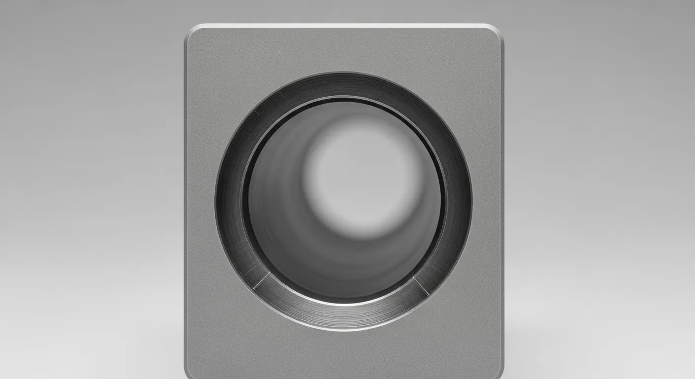
We run a 3-step inspection process for tight-tolerance plastic parts.
In-process gauging: Every bore was measured with a Mitutoyo bore gauge after the reaming operation. We used a 0.001mm resolution instrument. Any part outside ±0.025mm (tighter than spec) was flagged for re-inspection before moving to the next operation.
CMM final inspection: Every 10th part received a full CMM report on a Zeiss Contura CMM. We measured 14 features per part including bore diameter, wall thickness at 3 positions, channel alignment, and boss position. All 20 CMM-inspected parts passed 100%.
Surface finish verification: We used a Mahr MarSurf contact profilometer to check Ra values on bore surfaces. All parts measured between Ra 0.62 and Ra 0.78 µm, well within the Ra 0.8 µm requirement.
Final inspection: 200 parts shipped. 199 passed first-pass inspection (99.5%). One part had a minor surface inclusion in the raw PEEK stock, caught by our visual inspector before shipping. It was re-machined and delivered within the lead time window.
Results
The numbers tell the story.
- Delivery: All 200 parts delivered on day 11 of a 12-day lead time
- First-pass inspection rate: 99.5% (199/200 parts passed without rework)
- Client incoming inspection pass rate: 100% (client rejected zero parts)
- Bore diameter accuracy: All 200 bores within ±0.018mm actual variation (spec was ±0.030mm)
- Wall thickness: Minimum measured wall = 2.83mm (spec was 2.8mm minimum)
- Client outcome: Assembly line was running within 48 hours of receiving parts
The client has since placed a repeat order for 500 units with an additional turned variant added to the scope.
Why CNC Machining Was the Right Process
This question comes up on every plastic parts project. Here's the direct comparison:
Injection molding would have taken 6–8 weeks for tooling alone and required a minimum of 1,000+ parts to justify the mold cost. The client needed 200 units in 12 days. Injection molding was not an option.
3D printing (SLS or FDM PEEK): PEEK FDM printing is improving, but it still can't match the bore tolerances or surface finish this application required. A 3D printed bore would hold ±0.1–0.2mm at best. This application needed ±0.03mm. The density and mechanical properties of printed PEEK also don't match fully consolidated PEEK stock.
CNC machining cut directly from Victrex 450G PEEK rod, which is fully homogeneous, fully dense, and already rated to spec. We didn't have to compromise on material performance or part accuracy. For 200 units with tight tolerances and a 12-day window, CNC machining was the only process that could deliver.
This is consistent with how GD Prototyping approaches all plastic parts projects. We evaluate the geometry, tolerance, quantity, and timeline, then recommend the right process. You can see more examples in our CNC machining case study library.
FAQ
What plastics can you machine to tight tolerances?
We regularly machine PEEK, POM (Delrin), nylon PA66, UHMW-PE, polycarbonate, and ABS. For tolerances tighter than ±0.05mm, we recommend PEEK or POM. These materials are dimensionally stable and respond predictably to machining. Materials like nylon absorb moisture and can shift dimensions after cutting.
What's the tightest tolerance you can hold on plastic parts?
On CNC machined plastic parts, we routinely hold ±0.02mm on features like bores, shafts, and mating surfaces. The tolerance depends on the material, part geometry, and wall thickness. For very thin walls under 2mm, we recommend discussing your specific geometry with our engineers before confirming a tolerance target.
How many parts can I order as a minimum?
We don't have a fixed minimum. We've machined single prototype parts and batches of 1,000+. For orders under 10 parts, unit price is higher due to setup cost. For 50–500 parts, CNC machining is often the most cost-effective option before injection molding becomes viable.
Can you machine plastic parts from my supplied material?
Yes. We accept customer-supplied stock in most standard bar, plate, and rod sizes. We recommend confirming dimensions and grade before shipping. Victrex-grade PEEK and DuPont Delrin are the two most common customer-supplied materials we work with.
How do I get a quote for plastic CNC machining?
Send us your CAD file (STEP or IGES preferred), the required material grade, key tolerances, surface finish, and quantity. We'll respond within 12 hours with a detailed quote. You can also explore our CNC machining service page or visit our contact page to submit your inquiry directly.
Conclusion
This project is a good example of what CNC machining service for plastic parts actually involves at a technical level. It's not just programming a tool path and pressing start. It requires material annealing, thermal management, sequence planning, and in-process measurement to hit ±0.03mm on a complex geometry.
Our team solved two real problems, both found early enough to prevent a single client rejection. We delivered 200 PEEK housings, 11 days out of a 12-day window, with zero rejected parts at incoming inspection.
If you're working on a plastic parts project that requires tight tolerances, engineering-grade materials, or fast delivery, we'd like to look at your drawings. Explore our CNC machining case studies to see more project examples, or contact GD Prototyping for a quote within 12 hours.
