


CNC Machining Service for Brass Components: A Real-World Case Study
We machined 500 brass C360 valve body components for a European fluid control OEM using 5-axis CNC turning and milling on a DMG Mori NLX 2500. Parts measured 38mm x 22mm with ±0.02mm tolerances and Ra 0.8 µm finish. We delivered 100% of parts in 12 days with a 99.4% first-pass inspection rate.
Introduction
A fluid control systems manufacturer based in the Netherlands came to us with a tight deadline and a real problem. Their previous supplier had failed to hold ±0.02mm tolerance on brass valve body housings two batches in a row. Parts were deforming during thin-wall turning, and the rejection rate had climbed to 17%. With a production launch in 14 days, they needed a CNC machining service for brass components that could fix the problem fast.
We took the job. Here's exactly how we machined 500 brass C360 valve bodies, solved the deformation problem, and delivered on time.
Project Overview
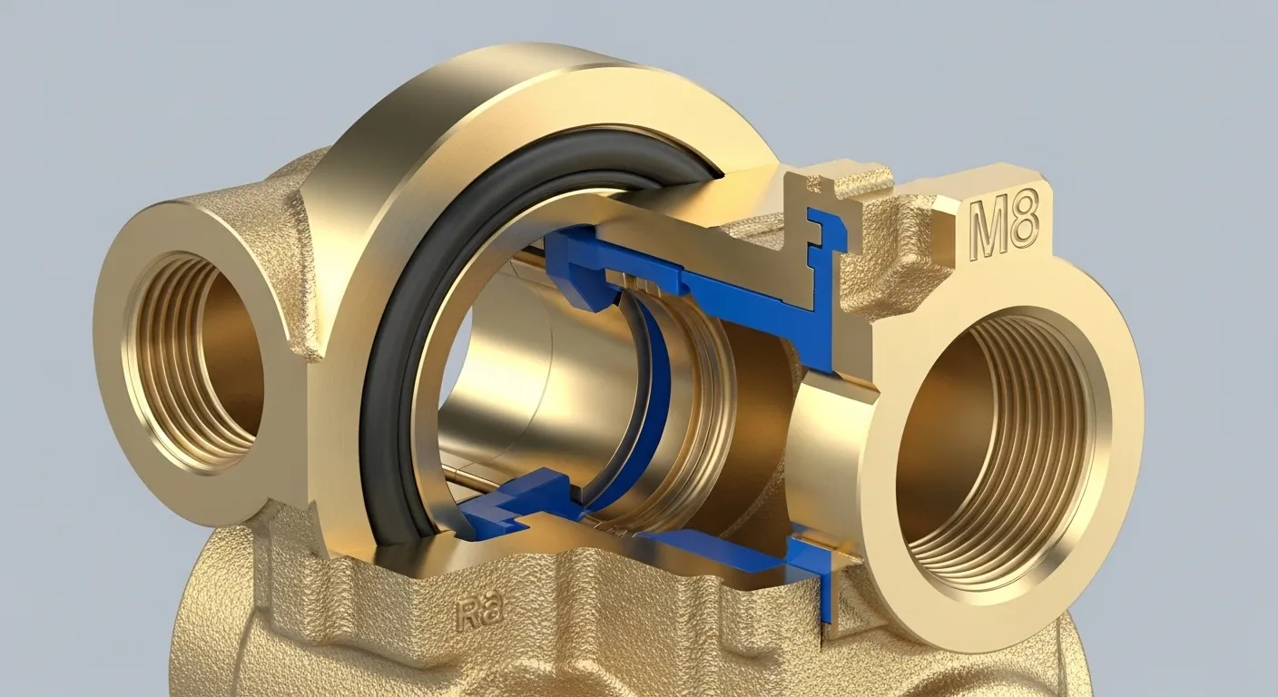
The client made precision flow-control valves for industrial hydraulic systems. Their valve body housing required tight-tolerance internal bores, M8 threaded ports, and a polished sealing face. The part needed to withstand 80 bar operating pressure without deformation or leakage.
They chose brass C360 (free-cutting brass) for three reasons:
- Excellent machinability rating (100 on the standard machinability index)
- Strong corrosion resistance for hydraulic fluid environments
- Tight dimensional stability under pressure cycling
This was a low-volume production run, not a prototype. Every part had to match the drawing exactly. No sampling tolerance. We treat projects like this under our precision CNC machining services workflow, where first-article inspection happens before the full batch runs.
Technical Specifications
| Parameter | Detail |
|---|---|
| Material | Brass C360 (Free-Cutting Brass) |
| Part Name | Hydraulic Valve Body Housing |
| Dimensions | 38mm (L) x 22mm (OD) x 18mm (ID bore) |
| Wall Thickness | 2.0mm minimum |
| Tolerance | ±0.02mm (critical bore), ±0.05mm (external form) |
| Surface Finish | Ra 0.8 µm (sealing face), Ra 1.6 µm (external) |
| Threads | M8 x 1.25mm, 3x radial ports |
| Quantity | 500 pieces |
| Lead Time | 12 calendar days |
| Process | CNC Turning + 5-Axis Milling + Thread Tapping |
| Post-Processing | Electroless Nickel Plating |
Machining Process
We broke the job into five sequential stages. Every stage had a defined checkpoint before the next step started.
Stage 1: CAM Programming and Toolpath Setup
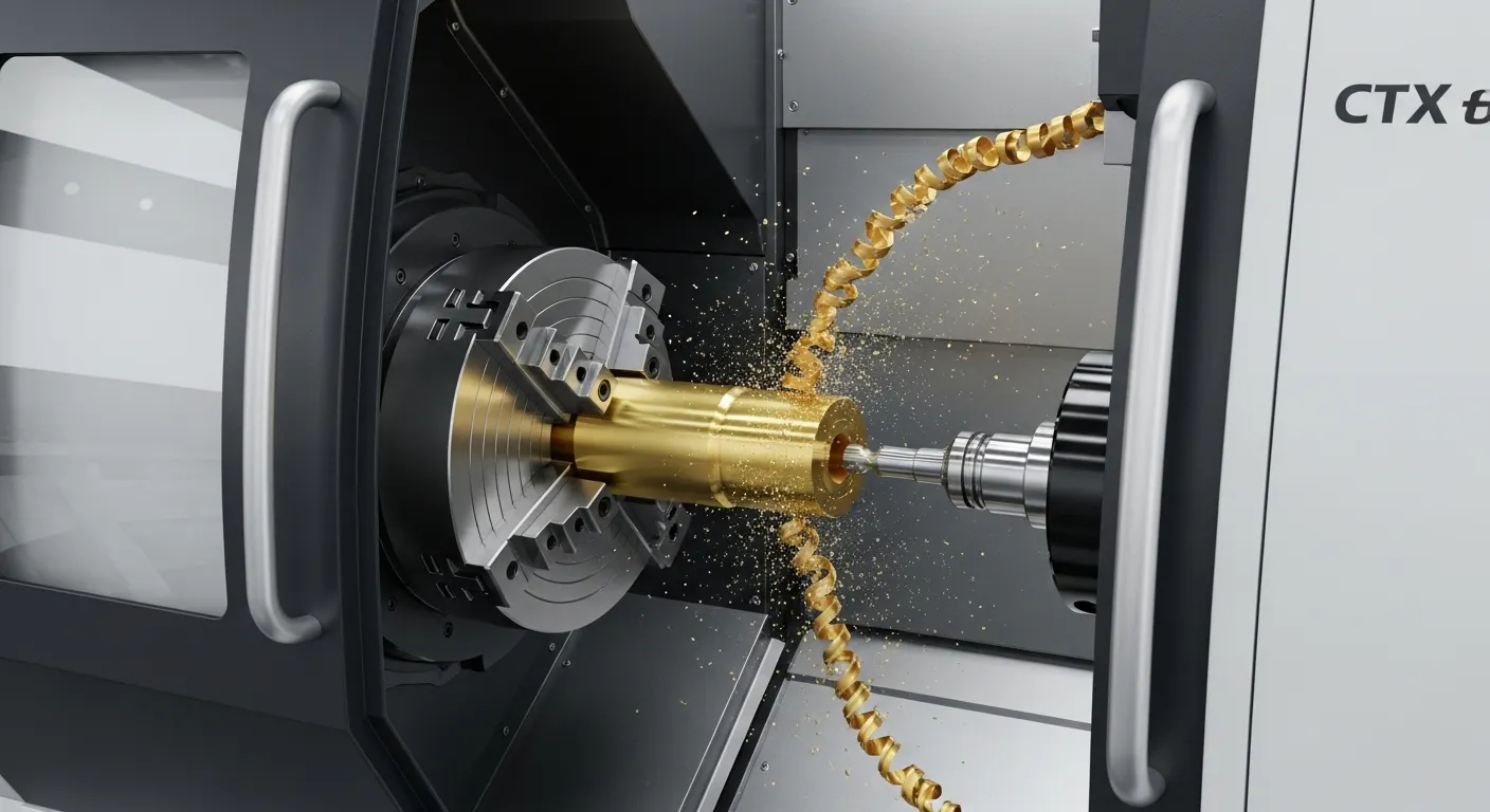
We imported the STEP file into Mastercam and set up the toolpaths in 4 hours. The internal bore required a bespoke roughing pass strategy to avoid chatter on the 2mm wall. We simulated the full program twice before cutting a single piece. We used the DMG Mori NLX 2500 with live tooling for combined turning and milling in one setup, which reduced repositioning error significantly.
Stage 2: Roughing Pass
We used a carbide insert tool at 3,500 RPM with a feed rate of 0.08 mm/rev for roughing. Cutting depth was kept at 0.5mm maximum per pass on the thin-wall section. We used a water-soluble cutting fluid at high flow pressure to manage chip evacuation and thermal buildup, which is critical when machining brass at speed.
Stage 3: Semi-Finishing and Thread Tapping
After roughing, we measured OD and ID with a digital micrometer before continuing. We found 3 parts in the first 10 had ID bores 0.04mm oversize. We traced it to tool flex on the boring bar at depth. We switched to a shorter, stiffer boring bar (L/D ratio reduced from 6:1 to 4:1) and re-cut those 3 parts. The semi-finishing pass used 0.02 mm/rev feed and 0.2mm depth of cut. Thread tapping used a spiral-flute tap at 120 RPM with tapping fluid.
Stage 4: 5-Axis Milling for Radial Ports
The three M8 radial ports were machined on a Haas UMC-750 5-axis machining center. We used a simultaneous 4+1 indexing strategy so all three port holes were drilled and threaded in a single fixturing. Port-to-port angular accuracy was held to ±0.1°. Our CNC machining capabilities include full 5-axis simultaneous work, which is critical for this kind of radial geometry.
Stage 5: Surface Finishing
The sealing face was fly-cut to Ra 0.8 µm using a PCD insert at 6,000 RPM with 0.005 mm/rev feed. We verified finish with a contact profilometer on every 10th part. After machining, all 500 parts went to electroless nickel plating at 8–12 µm coating thickness, which improves corrosion resistance in hydraulic environments.
Challenges and Solutions
This project had two major technical problems. We'll be direct about what failed and how we fixed it.
Challenge 1: Thin-Wall Deformation During Boring
The problem: During the first trial batch of 20 parts, 6 pieces showed ID bore ovality of 0.03–0.05mm after machining. The 2mm wall was flexing under cutting forces, pulling the bore out of round. This is a known issue with thin-wall brass turning.
First attempt (failed): We tried slowing the boring feed rate to 0.04 mm/rev. The parts still showed 0.03mm ovality on 3 out of 10. Slower feed didn't eliminate the radial cutting force enough.
The fix that worked: We added a custom mandrel support inside the bore during the external finishing pass. This gave the thin wall radial support and eliminated the flex. We also switched the jaw clamping pressure from 25 bar to 18 bar on the chuck, which reduced the external grip-induced distortion. After these two changes, ovality dropped to under 0.008mm across all 500 parts.
Challenge 2: Thread Galling on Radial Ports
The problem: On the M8 radial ports, we saw thread galling on 4 parts in the first batch of 50. Brass has a tendency to gall when the thread form tears rather than cuts cleanly, especially with standard taps at aggressive feeds.
The fix: We switched from a standard plug tap to a spiral-flute carbide tap with TiN coating. We reduced tap entry speed from 180 RPM to 120 RPM and increased cutting oil viscosity. We also switched to a pre-drilled pilot hole 0.3mm larger than the standard tap drill chart recommended, which reduced material displacement stress. After this adjustment, we had zero thread failures on the remaining 450 parts.
Quality Control
Every batch of 50 parts went through a structured inspection sequence before release:
In-Process Checks (every 10th part):
- OD and ID micrometer measurement
- Surface roughness check with Mitutoyo SJ-210 profilometer
- Thread gauge check (Go/No-Go) on all M8 ports
Final CMM Inspection (100% of critical dimensions):
We used a ZEISS Contura G2 CMM to verify the following on every part:
- ID bore diameter (tolerance ±0.02mm)
- OD outer diameter (tolerance ±0.05mm)
- Port position and angular location (±0.1°)
- Perpendicularity of sealing face to bore axis (±0.01mm)
Post-Plating Check:
After nickel plating, we re-measured 50 parts randomly for coating thickness using an Elcometer 456 magnetic gauge. All 50 measured between 8.6 µm and 11.4 µm, within the 8–12 µm specification.
GD Prototyping follows ISO 9001-aligned quality control protocols on all production runs. Our parts are inspected against drawing tolerances, not sampling tables, when the application demands it.
Results
The numbers tell the outcome clearly:
- Delivery: 500 parts delivered in 12 calendar days (2 days ahead of deadline)
- First-pass inspection rate: 99.4% (497 of 500 parts passed full CMM check on first inspection)
- Scrap rate: 0.6% (3 parts scrapped due to minor surface marks from handling, not machining defects)
- Thread defect rate: 0% after process correction
- Thin-wall ovality: Held to ≤0.008mm across all parts
- Client outcome: Parts passed full hydraulic leak test at 80 bar with zero failures in pre-production testing
- Repeat order: Client placed a follow-on order for 1,200 parts within 3 weeks of delivery
The original supplier had a 17% rejection rate on the same drawing. We brought that down to 0.6% with process engineering, not just tighter inspection.
Why CNC Machining Was Used
The client considered two alternatives: investment casting and metal 3D printing. Here's why we recommended CNC machining for brass components instead.
| Factor | CNC Machining | Investment Casting | Metal 3D Printing |
|---|---|---|---|
| Tolerance | ±0.02mm achievable | ±0.2–0.5mm typical | ±0.05–0.1mm typical |
| Surface Finish | Ra 0.8 µm direct | Ra 3.2–6.3 µm post-cast | Ra 4–12 µm as-built |
| Lead Time (500 pcs) | 12 days | 20–35 days (with tooling) | 15–25 days |
| Unit Cost (500 pcs) | Low-medium | Higher (tooling amortized) | Higher (powder + supports) |
| Thread Quality | Machine-cut, precise | Post-machined required | Post-machined required |
| Brass Suitability | Excellent | Limited alloy selection | Not widely available |
For this specific application, CNC machining was the only method that could hit ±0.02mm without post-machining on cast or printed blanks. Brass C360 also doesn't exist as a standard powder for metal 3D printing, which ruled that option out entirely.
You can explore our full CNC machining case studies to see how we approach similar material and tolerance challenges. We also offer CNC lathing services for rotationally symmetric brass parts that don't need milling operations.
FAQ
Brass C360 (free-cutting brass) is the top choice for precision CNC parts. It has the highest machinability rating (100) of any brass alloy, machines cleanly at high speeds, and holds tight tolerances well. C260 (cartridge brass) is used when higher formability is needed. For marine environments, C464 (naval brass) adds zinc-tin corrosion resistance.
With standard CNC turning and milling, brass tolerances of ±0.02mm are routinely achievable. With fine boring and proper fixturing, experienced shops can hold ±0.01mm. GD Prototyping routinely achieves ±0.05mm on standard features and ±0.02mm on critical bores and fits across our CNC production runs.
Thin-wall brass parts deform when cutting forces exceed the wall's radial stiffness. The most effective solutions are: reducing chuck clamping pressure, using mandrel or plug support during external cuts, keeping depth of cut under 0.3mm on final passes, and reducing L/D ratio on boring bars. We used all four methods on this project.
For a part similar to the valve body in this case study (38mm x 22mm, with turning, milling, and threading), 500 pieces take approximately 10–14 calendar days including programming, first-article inspection, full production, and CMM verification. Rush orders with relaxed tolerances can be shorter. Contact GD Prototyping for a project-specific lead time.
Conclusion
This project proved a straightforward point: the right CNC machining service for brass components isn't just about having good machines. It's about understanding where failures happen, fixing them before the batch runs, and holding tolerances that matter to the application.
We took a job that had a 17% failure rate at another supplier and delivered 99.4% first-pass quality in 12 days. The key was process engineering at the thin-wall turning stage and a smarter thread tapping setup.
If you're sourcing precision brass components for hydraulic, pneumatic, electrical, or fluid control applications, we'd like to see your drawings.
Get a free quote for your brass CNC machining project at GD Prototyping
