
CNC Machining for Connectors: Materials, Tolerances, and How to Get It Right
CNC machining produces precision connector housings, contacts, and shells with tolerances as tight as ±0.005mm. It works with aluminum, brass, stainless steel, and PEEK. It's the right process for low-to-mid volumes (1–10,000 units) where dimensional accuracy and fast lead times matter more than per-unit cost.
Why Connectors Demand Precision Machining
Connectors fail at the interface. A bore diameter that's 0.03mm too wide causes electrical contact resistance to spike. A thread that's 0.02mm shallow strips under torque. A housing that's 0.05mm out of square misaligns pins and creates intermittent signal loss.
CNC machining for connectors solves these problems because it cuts from solid billet material and holds tolerances that casting and injection molding simply can't match without expensive post-machining. For engineers sourcing connector components, CNC machining is the default process for anything requiring bore tolerances tighter than ±0.05mm.
What Types of Connectors Use CNC Machining?
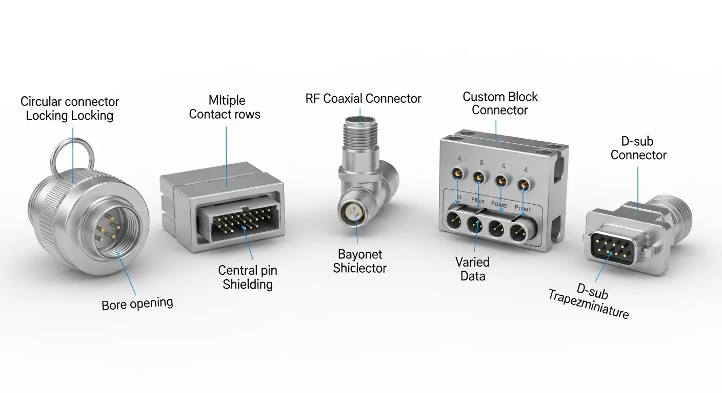
CNC machining applies across a wide range of connector types. The most common include:
- Circular connector housings for military, aerospace, and industrial automation (MIL-DTL-38999, M12, M8 profiles)
- RF and coaxial connector bodies (SMA, N-type, BNC) requiring concentricity within 0.01mm
- D-sub and rectangular connector shells for panel-mount industrial equipment
- PCB edge connector inserts and high-density backplane housings
- Custom connector blocks for PLC systems, hydraulic solenoids, and sensor arrays
- Medical device connectors requiring Ra 0.4 µm surface finish and biocompatible materials
Each type has different critical dimensions, but all share one requirement: consistent, repeatable accuracy across every unit in the batch. Our CNC machining services cover all of these connector types from prototype through pilot production.
Best Materials for CNC Machined Connectors
Choosing the wrong material is the most common mistake in connector sourcing. Here's how the four main options compare:
| Material | Best For | Tensile Strength | Machinability | Typical Finish |
|---|---|---|---|---|
| Aluminum 6061-T6 | Lightweight housings, automation connectors | 310 MPa | Excellent | Anodize, Alodine |
| Brass C36000 | RF, electrical, and coaxial connectors | 385 MPa | Excellent | Nickel plate, bare |
| Stainless 316L | Marine, chemical, high-cycle connectors | 515 MPa | Moderate | Passivation, electropolish |
| PEEK | High-temp, electrically isolating connector bodies | 100 MPa | Good | Bare, light bead blast |
Aluminum 6061-T6 is the most machined connector material at GD Prototyping. It cuts fast, anodizes cleanly, and hits ±0.01mm bore tolerances reliably. For connectors in sealed IP67 enclosures, Type II hard anodize at 15–20 µm is the standard surface treatment.
Brass C36000 is the go-to for RF connector bodies. Its natural conductivity, 28% IACS, supports signal integrity while its machinability rating of 100% (the benchmark) makes it economical to machine to tight concentricity specs.
You can review finished examples of both aluminum and brass connector components in our CNC machining case study library.
Tolerances You Can Expect from CNC Machined Connectors
Tolerance capability depends on geometry, material, and machine setup. Here are realistic benchmarks:
- Standard CNC milling tolerance: ±0.05mm — suitable for non-critical connector features like overall housing envelope and mounting holes
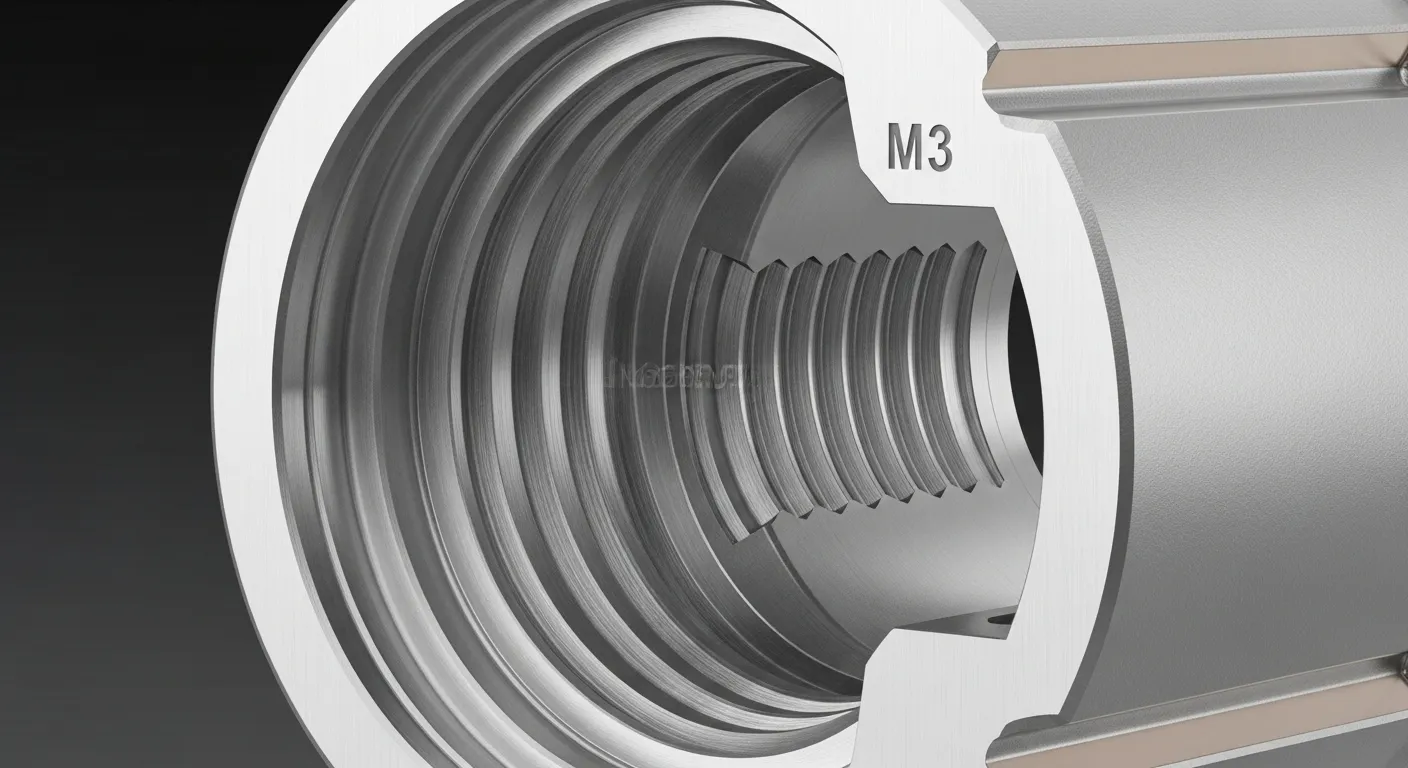
- Precision bore reaming: ±0.005mm to ±0.01mm — required for pin retention bores, contact seats, and mating interface diameters
- Thread tolerances: ±0.02mm on M2 to M4 threads when using rigid tapping with thread gauges per ISO 965-1
- Surface finish: Ra 0.8 µm standard, Ra 0.4 µm achievable with PCD tooling and low-feed finishing passes
- Concentricity for RF connectors: within 0.01mm TIR on outer conductor to inner bore axis
For most industrial connector housings, ±0.01mm on bore diameters and ±0.02mm on thread features covers all functional requirements.
Key Design Considerations for CNC Machined Connectors
Getting a connector machined right starts at the design stage. Here are the most important factors to get right before you send a drawing:
Wall thickness
Keep minimum wall thickness at 1.5mm or above for aluminum connector housings. Walls thinner than 1.2mm deflect during machining and push bore tolerances out of spec. If your design requires 0.8mm walls, discuss vibration damping fixturing with your supplier before they quote.
Bore depth-to-diameter ratio
Bores deeper than 4x their diameter require extended reamers, which have more runout risk. For connector pin retention bores with a 6mm diameter, keep depth under 24mm for standard tolerances. Deeper than that, flag it explicitly on the drawing.
Anodize compensation
Type II anodize grows 0.010–0.015mm into the surface per side. For a 6.35mm bore, the pre-anodize diameter must be 6.375–6.380mm to land at 6.350mm post-anodize. Many buyers don't specify this on drawings. It's the leading cause of bore spec failures in anodized connector housings.
Thread relief grooves
Add a 0.3mm wide x 0.3mm deep thread relief groove at the base of all blind threaded ports. It prevents tap breakage and improves thread engagement length.
GD&T callouts
Specify true position, concentricity, and perpendicularity on your drawing where they matter, not just dimensional tolerances. A bore that's ±0.01mm in diameter but 0.05mm off-axis still fails.
CNC Machining Process for Connector Parts: Step by Step
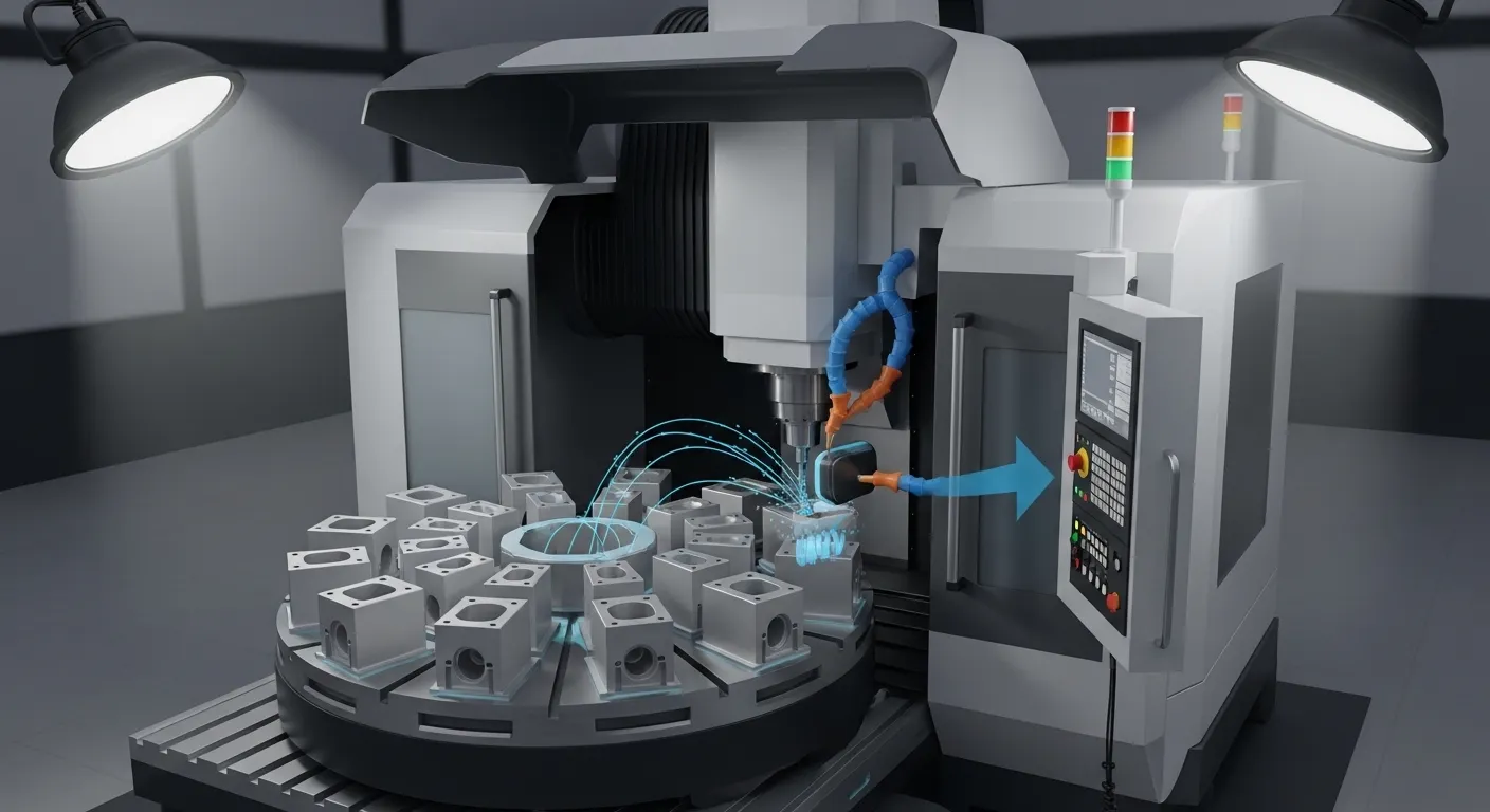
Understanding the process helps you communicate better with your supplier and avoid costly revision loops.
1. CAM programming
The machinist programs toolpaths in software like Mastercam or Fusion 360. For connectors, this includes separate programs for roughing, semi-finishing, bore reaming, and threading. A well-written CAM file accounts for tool deflection on thin walls and chip evacuation in deep pockets.
2. Fixture and workholding
Connectors are small, often under 50mm in any dimension. Workholding matters enormously. Soft jaws gripping non-critical surfaces prevent clamping deformation. Some connector housings require custom fixtures to machine all features in one setup, which saves the re-registration error of multiple setups.
3. Roughing
Bulk material is removed fast, leaving 0.3–0.5mm of stock on precision surfaces. High-pressure coolant (50–70 bar, through-spindle) clears chips and prevents the thermal expansion that warps small aluminum parts.
4. Finishing and reaming
A final finishing pass with a sharp, fresh tool brings surfaces to final dimension. Bores are reamed, not just milled, for the tightest tolerances. PCD reamers achieve Ra 0.4–0.6 µm in aluminum and hold ±0.005mm diameter.
5. Threading
Rigid tapping in a CNC cycle, not hand tapping, is mandatory for connector thread specs. Rigid tapping holds true position within 0.015mm per ISO 965-1 requirements.
6. Deburring and cleaning
Connectors have complex internal geometry. Ultrasonic cleaning after deburring removes all chips and swarf from internal channels before inspection. Any chip left inside a connector housing becomes a contamination risk in the final assembly.
7. Surface treatment
Anodize, nickel plating, or passivation depending on the material and application. Surface treatment specs must be on the drawing with layer thickness callouts so the machinist compensates bore and thread dimensions correctly before finishing.
How to Compare CNC Machining vs. Other Connector Manufacturing Methods
| Factor | CNC Machining | Die Casting | Injection Molding | Metal 3D Printing |
|---|---|---|---|---|
| Tolerance | ±0.005–0.05mm | ±0.1–0.3mm | ±0.1–0.5mm | ±0.05–0.2mm |
| Min. Order Qty | 1 unit | 500–1,000+ | 500–1,000+ | 1 unit |
| Lead Time | 3–10 days | 4–8 weeks (with tooling) | 4–8 weeks (with tooling) | 5–14 days |
| Tooling Cost | None | $8,000–$25,000 | $5,000–$20,000 | None |
| Best Volume | 1–10,000 units | 10,000+ units | 10,000+ units | 1–100 units |
| Surface Finish | Ra 0.4 µm+ | Ra 1.6–3.2 µm | Ra 0.8–1.6 µm | Ra 6–12 µm (pre-finish) |
CNC machining is the clear choice when you need tight tolerances, fast delivery, and no tooling investment. Die casting wins at volumes above 10,000 units once tooling cost is amortized. Injection molding suits non-conductive plastic connector bodies at high volumes. Metal 3D printing works for complex internal geometries at very low quantities where per-part cost is not the priority.
What to Include in Your Connector Drawing for an Accurate Quote
Suppliers quote faster and more accurately when drawings are complete. Include:
- Material grade (not just "aluminum," specify 6061-T6 or 7075-T6)
- All tolerances explicitly called out, especially bore diameters and thread specs
- Surface finish Ra value on every machined surface that matters
- Surface treatment with layer thickness callout (e.g., "Type II Anodize, 15–20 µm")
- GD&T for any concentricity, perpendicularity, or true position requirements
- Quantity and any future production volume expectations
- Required inspection documentation (first article inspection report, CMM report, material cert)
Send your drawings to GD Prototyping and we'll review them and return a quote within 12 hours.
Industries That Rely on CNC Machined Connectors
CNC machined connector components are used wherever precision mating interfaces are non-negotiable:
- Industrial automation: PLC connector blocks, sensor housings, servo motor feedback connectors
- Automotive: ECU connectors, EV battery management system housings, ADAS sensor interface blocks
- Aerospace and defense: MIL-spec circular connectors, avionics backplane components, radar waveguide interfaces
- Medical devices: Surgical instrument connectors, imaging system cable assemblies, implantable device interfaces
- Telecommunications: RF connector bodies, fiber optic ferrule housings, base station antenna interfaces
Each industry has its own standard specs and certifications, but the underlying machining requirements are consistent: tight tolerances, clean threads, and reliable surface finish batch after batch.
FAQ
How tight a tolerance can CNC machining hold on a connector bore?
With PCD reaming on aluminum 6061-T6, we hold bore tolerances to ±0.005mm. For steel and brass connector bodies, ±0.008mm to ±0.01mm is standard. The achievable tolerance depends on bore diameter, depth, wall thickness, and material. Always specify your critical tolerance on the drawing rather than relying on default machining tolerance.
What's the minimum quantity for a CNC machined connector order?
There's no minimum. We machine single prototypes through to production runs of 10,000+ units. For 1–10 prototypes, expect 3–5 day lead time. For 50–500 units, 5–8 days is typical. First-off samples are available before full batch production on request.
Do you provide material certificates for connector parts?
Yes. Material certifications (MTRs) are available for all orders on request. For aerospace and medical connector applications, we supply full traceability documentation including raw material heat lot, CMM dimensional reports, and surface treatment process records.
Can you machine connectors with undercuts and internal grooves?
Yes. 5-axis CNC machining handles undercuts, locking grooves, and internal features that would require multiple operations on a 3-axis machine. For deep internal grooves, we use custom-form tooling. Describe your geometry when requesting a quote and we'll confirm the approach before pricing.
What surface treatments work with CNC machined aluminum connectors?
Type II anodize (decorative, up to 25 µm), Type III hard anodize (wear-resistant, up to 50 µm), Alodine/chem film (MIL-DTL-5541, for conductivity with corrosion protection), nickel plating, and electroless nickel are all compatible with aluminum 6061-T6. We coordinate surface treatment through our partner network and handle dimensional compensation on bores and threads before finishing.
Get a Quote for Your Connector Project
CNC machining for connectors requires more than a capable machine. It requires experience with bore reaming sequences, anodize compensation, thread gauging, and fixture design for small complex parts.
GD Prototyping machines connector components from single prototypes to production batches with 5-axis capability, in-house CMM inspection, and 7–10 day standard lead times. Upload your drawings and get a free quote today. Our engineering team reviews every drawing before quoting and flags DFM issues before they become production problems.