
Vacuum Casting Tolerances: What to Expect
In product development, prototypes must do more than just look like the final product; they must function like it. For parts that need to fit together in a precise assembly, this functionality hinges on dimensional accuracy. Engineers and designers need to know, with confidence, how closely a manufactured part will match their original digital design. This is the critical role of dimensional tolerance. For vacuum casting, a process renowned for its speed and quality, understanding its realistic tolerance capabilities is key to leveraging its full potential.
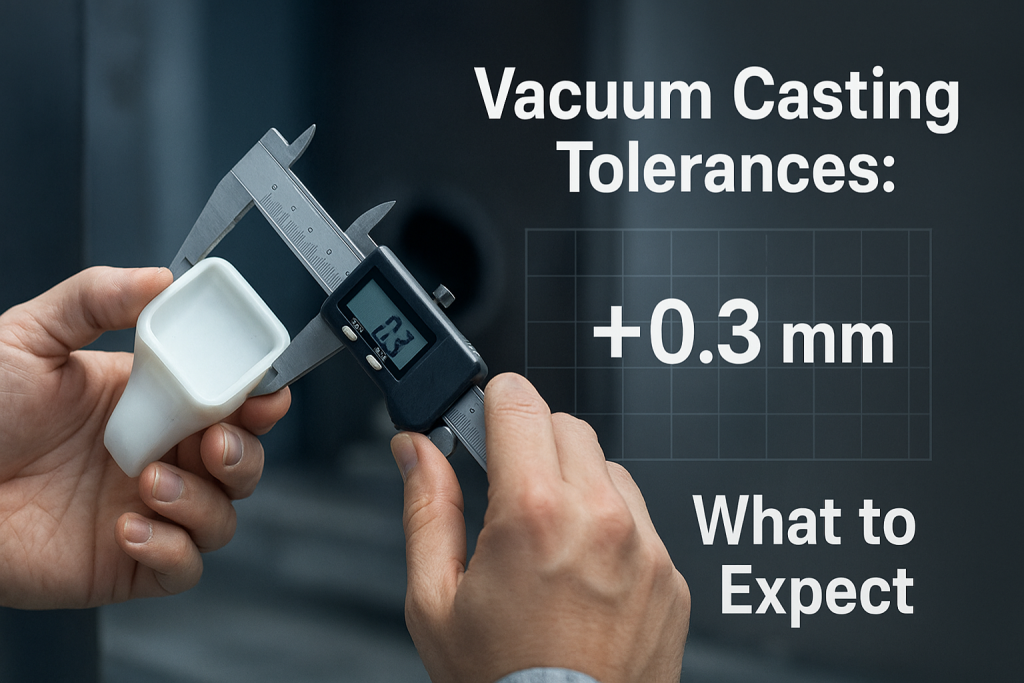
The typical dimensional tolerance for vacuum casting is ±0.3% of the nominal dimension, with a lower limit of ±0.3 mm on features under 100 mm. Tighter tolerances, often as good as ±0.15 mm, are possible on smaller, well-designed parts. However, this general rule provides a reliable baseline of what to expect from the process.
As an expert in precision vacuum casting, GD-Prototyping has a deep understanding of the factors that control and influence part accuracy. This guide provides a comprehensive overview of vacuum casting tolerances. We will explain the sources of variation, detail the specific tolerances you can expect, and offer practical advice on how to design parts for maximum accuracy.
The Chain of Accuracy: Sources of Variation in Vacuum Casting
The final tolerance of a vacuum cast part is not the result of a single variable. It is a cumulative stack-up of several small, predictable variations that occur at each stage of this multi-step process. An expert casting service understands this "chain of accuracy." They work to control and compensate for these variations at every step to produce the most precise part possible. Understanding this chain is essential for setting realistic expectations.
Where Do Tolerances Come From?
The journey from a digital file to a final part involves four key stages where dimensional shifts can occur.
Stage 1: The Master Pattern's Accuracy
The entire vacuum casting process begins with a physical master pattern. The final cast part can only be as accurate as this initial master. The master pattern is typically created using a high-resolution 3D printing technology, most commonly Stereolithography (SLA). Industrial-grade SLA machines are capable of producing parts with very high accuracy, often with tolerances as tight as ±0.1 mm. The precision of this initial master pattern sets the highest possible bar for the accuracy of the final cast parts.
Stage 2: Silicone Mold Shrinkage
The second stage involves creating a silicone mold from the master pattern. The two-part liquid silicone rubber used to create the mold undergoes a small, predictable amount of shrinkage as it cures from a liquid to a solid. This shrinkage rate is a known property of the specific silicone being used, typically around 0.1% to 0.2%. An experienced mold maker will compensate for this. They will often create the master pattern to be slightly oversized by this exact percentage. This ensures that after the silicone mold has shrunk, its internal cavity will be the perfect size.
Stage 3: Urethane Resin Shrinkage
This is the most significant source of dimensional variation in the process. The two-part polyurethane resins used to cast the final parts also shrink as they cure. This is a natural part of the chemical polymerization process. Different families of polyurethane resins have different shrinkage rates, ranging from as low as 0.15% to as high as 1% or more. A key part of an expert's job is to select a high-quality, low-shrinkage resin that meets the project's mechanical requirements. They will also use their process knowledge to manage the curing temperature and pressure to minimize the effects of this shrinkage.
Stage 4: Mold Degradation Over Time
The fourth and final factor is the lifespan of the silicone mold itself. A silicone mold is a "soft tool." It is not made of rigid steel. With each part that is cast and demolded, the mold is subjected to thermal and mechanical stress. This causes a very small amount of wear and tear. Over the course of its 20-25 shot lifespan, the mold can begin to deform or degrade slightly. This means a part cast later in the run (e.g., part #20) may have a slightly different tolerance than the first part from the mold. This is a key aspect of Silicone Mold Life in Vacuum Casting.
The Vacuum Casting Tolerances Spec Table
This table provides a clear, practical guide to the standard, achievable tolerances for parts made via vacuum casting. These values represent a good baseline for general engineering purposes and can be used for initial design and planning.
| Nominal Dimension Range | Standard Tolerance | Notes / Key Considerations |
| 0 – 100 mm (0 – 4 in) | ±0.3 mm (±0.012 in) | This is the baseline tolerance for most features. Tighter tolerances (±0.15 mm) are often achievable on well-designed smaller features. |
| 100 – 500 mm (4 – 20 in) | ±0.3% of the dimension | For larger dimensions, the tolerance becomes a percentage of the length due to the cumulative effect of material shrinkage. |
| 500+ mm (20+ in) | ±0.4% of the dimension | Very large parts are more susceptible to minor warping and shrinkage variations, requiring a slightly wider tolerance range. |
| Typical Wall Thickness | ±0.2 mm (±0.008 in) | This tolerance applies to the thickness of a designed wall section. |
| Hole Diameters | ±0.2 mm (±0.008 in) | For standard-sized holes. Very small or very deep holes may require a wider tolerance. |
| Part-to-Part Repeatability | ~ ±0.15 mm | The expected variation between identical parts cast from the same mold. |
A Deep Dive into Factors that Influence Final Tolerance
The numbers in the spec table are a general guide. The actual tolerance achievable for a specific part depends heavily on its unique characteristics. An expert service provider will analyze these factors to provide a more precise tolerance expectation for a given design.
Part Size
The overall size of the part is a major factor. As noted in the table, the tolerance for larger features is expressed as a percentage. A large part has more volume and will experience a greater absolute amount of shrinkage as it cures. A 500 mm long part, for example, will shrink much more in absolute terms than a 50 mm part, even if the shrinkage rate is the same. This makes it more challenging to hold very tight tolerances on large components.
Part Geometry
The shape of the part has a profound impact on its final dimensional accuracy.
- Wall Thickness: A part with a consistent, uniform wall thickness will cool and shrink in a predictable and uniform way. This leads to a stable and accurate part. A part with both very thick and very thin sections will cool unevenly. This creates internal stresses that can cause the part to warp or distort, which is a major source of dimensional error.
- Large, Flat Surfaces: Large, unsupported flat surfaces are the most likely features to warp or sag during the curing process. This can affect the flatness tolerance of the part.
- Unsupported Features: Tall, thin, or delicate features that are not well-supported by the surrounding geometry can sometimes deform slightly under their own weight during the curing cycle.
Material Choice (Resin Properties)
The specific polyurethane resin selected for the project has a direct impact on the achievable tolerance.
- Shrinkage Rate: Different resin formulations have different published shrinkage rates. A skilled service provider will stock a range of high-quality resins, including low-shrinkage formulations that are specifically designed for high-accuracy applications.
- Hardness (Durometer): The hardness of the final part affects how it is measured. A hard, rigid part (e.g., Shore 85D) can be measured easily with calipers or a CMM. A very soft, flexible part (e.g., Shore 40A) is much more difficult to measure accurately, as it can deform under the pressure of the measuring instrument. Therefore, the stated tolerance for very soft parts is often slightly wider. Choosing the right material from the Vacuum Casting Shore Hardness Chart can impact the final measurable tolerance.
The Quality of the Master Pattern
The final part can never be more accurate than the master pattern it was molded from. The quality of the initial SLA 3D print and, critically, the skill of the model maker who hand-finishes the pattern are paramount. An expertly prepared master pattern with a perfect surface and sharp details is the essential starting point for producing accurate cast parts.
Designing for Tighter Tolerances in Vacuum Casting
While vacuum casting has its inherent tolerance range, engineers can take specific steps during the design phase to maximize the accuracy of their parts. This is a core part of Design for Manufacturability (DFM).
How Can Engineers Improve the Accuracy of Their Cast Parts?
Following these best practices will result in more stable and predictable components.
- Design with uniform wall thickness. This is the most important rule. A consistent wall thickness ensures uniform cooling and shrinkage, which is the best way to prevent warping and dimensional distortion.
- Add ribs or gussets to support large, flat surfaces. Instead of making a large surface thick and heavy, keep the wall thin and add a network of small support ribs to the non-cosmetic side. This increases stiffness and prevents warping without adding mass.
- Incorporate generous radii on all corners. Sharp internal corners create stress concentrations and can lead to warping or cracking. Adding a smooth radius to all corners improves the part's strength and dimensional stability.
- Clearly indicate critical dimensions on your drawing. If a specific feature, like the distance between two mounting holes, is critical for your assembly, it should be clearly marked on your 2D engineering drawing. This allows the service provider to pay special attention to that feature during production and inspection.
- Discuss critical tolerances with your manufacturing partner upfront. An open discussion about your part's functional requirements allows the casting expert to make specific recommendations. They may suggest a different material or a slight design modification to achieve your goals.
The Importance of Post-Machining for Critical Features
For features that require a tolerance tighter than the standard vacuum casting process can provide (e.g., a precision bearing bore or a press-fit pin hole), the best practice is to combine processes. The part can be designed with these features slightly undersized. After the part is cast, it can be put on a CNC machine to have those critical features machined to a very high tolerance. This hybrid approach gives you the best of both worlds: the speed and low cost of vacuum casting for the overall shape, and the high precision of CNC machining for the critical features.
Consistency: Part-to-Part Repeatability
For a low-volume production run, it is important to understand how consistent the parts will be from the beginning to the end of the run.
How Consistent are Parts from the Same Mold?
Because vacuum casting uses a soft silicone mold, there will be very slight dimensional variations from the first part to the 25th part. The repeated mechanical and thermal stresses of the process cause the mold to wear slightly with each cycle. This can lead to a very minor "tolerance drift" over the course of a production run. A professional service provider will inspect the parts throughout the process to ensure every part stays within the specified tolerance.
This is a key difference when evaluating Vacuum Casting vs Injection Molding for 20–300 Parts. Injection molding uses a hard steel tool that does not wear, resulting in exceptional part-to-part repeatability. To learn more about the complete process, please see our guide, What Is Urethane Casting? A Practical Guide.
Conclusion
Vacuum casting is a remarkably accurate and precise manufacturing process, especially considering its speed and low tooling cost. By understanding the standard achievable tolerances and the key factors that influence them, engineers can design parts with confidence. The process is more than capable of producing high-fidelity prototypes and low-volume production parts that fit and function correctly in complex assemblies.
The key to success lies in good design practices and a collaborative partnership with an expert service provider. A knowledgeable partner can provide critical feedback during the design phase. They can select the right materials and control the process to maximize accuracy and deliver parts that meet or exceed expectations. At GD-Prototyping, our team is committed to this level of quality and expertise.