


Tight Tolerance CNC Machining: How We Held ±0.01mm on an Automotive Sensor Housing
A European automotive supplier needed 150 aluminum sensor housings with wall thicknesses of 1.2mm and bore tolerances of ±0.01mm. We machined them from Aluminum 6061-T6 using 5-axis CNC milling on a DMG Mori DMU 65 monoBLOCK. Final inspection showed a 99.3% first-pass yield. Parts shipped in 12 working days, 2 days ahead of schedule.
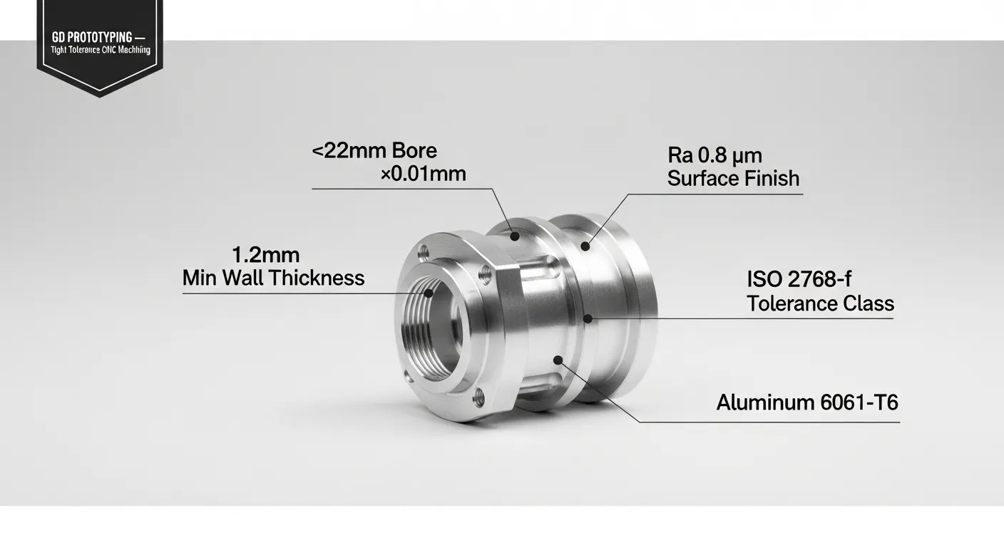
Introduction
The client sent us a 2D drawing that most shops turned down.
It showed an aluminum sensor housing, 87mm x 54mm x 32mm, with a central bore tolerance of ±0.01mm and wall sections as thin as 1.2mm. The part connects directly to a fuel injection control module in a next-gen gasoline engine. Dimensional drift of even 15 microns would cause seal failure under operating pressure of 180 bar.
Two previous suppliers failed quality inspection. We accepted the job, ran a full DFM review in 48 hours, and delivered on time. Here's exactly how we did it, step by step.
This is a real example of what tight tolerance CNC machining service looks like in a production environment — not a spec sheet, but an actual project.
Project Overview
The client is a Tier 2 automotive supplier based in Central Europe. They produce sensor sub-assemblies for petrol and hybrid powertrains. Their OEM customer required dimensional compliance per ISO 2768-f (fine) with additional GD&T callouts at the bore and mating face.
Key project requirements:
- 150 units for functional validation and pre-production testing
- Zero visible defects on the anodized outer surface
- CMM report for every batch of 25 parts
- All parts must fit a proprietary test fixture within 0.015mm positional tolerance
The application demanded tight tolerance CNC machining service with no room for variance. One rejected part could delay engine dyno testing by two weeks, costing the client an estimated €35,000 in project delay.
Technical Specifications
| Parameter | Details |
|---|---|
| Material | Aluminum 6061-T6 |
| Overall Dimensions | 87mm x 54mm x 32mm |
| Central Bore Diameter | Ø22.000mm (+0.010 / -0.000) |
| Wall Thickness (minimum) | 1.2mm |
| Tolerance Class | ISO 2768-f |
| Critical Bore Tolerance | ±0.01mm |
| Surface Finish | Ra 0.8 μm (bore), Ra 1.6 μm (external) |
| Surface Treatment | Type II hard anodize, 15 μm ±2 μm |
| Quantity | 150 units |
| Lead Time | 14 working days (delivered in 12) |
| Primary Process | 5-axis CNC milling + CNC turning |
| Machine Used | DMG Mori DMU 65 monoBLOCK |
| Inspection Method | Zeiss CONTURA G2 CMM |
Machining Process
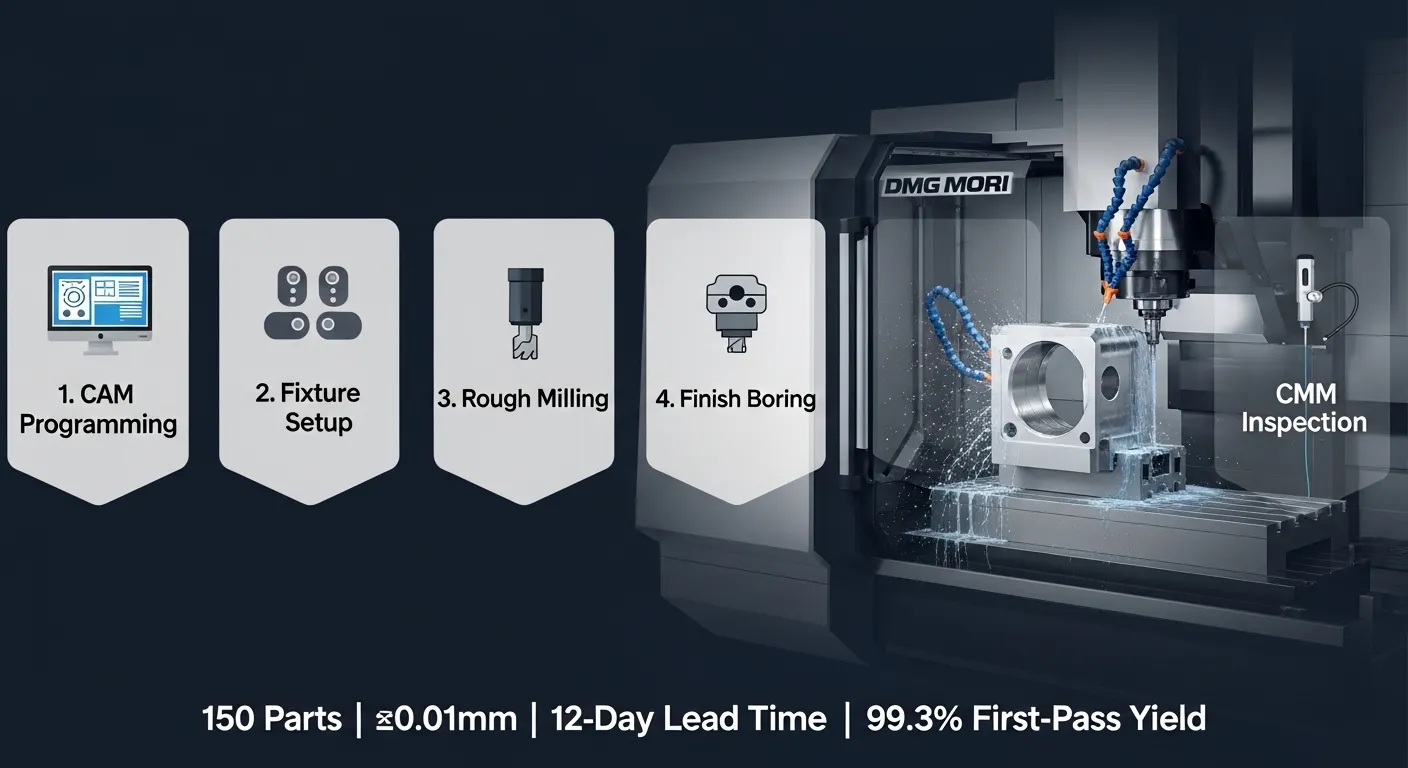
We broke the job into six defined stages. Each stage had a pass/fail checkpoint before moving forward.
Stage 1: CAM Programming and Simulation
Our CAM engineer used Mastercam 2025 to build the toolpath. We ran a full material removal simulation to identify collision risk zones around the 1.2mm wall sections. Tool stick-out was kept under 3x diameter ratio throughout to minimize vibration.
Stage 2: Fixture Design and Workholding
We designed a custom soft jaw fixture that clamps the part at the base, leaving the thin walls unsupported from the side. This reduced clamping-induced deflection to under 4 microns, verified with a dial indicator at setup.
Stage 3: Rough Milling
We removed 78% of the stock volume in the roughing pass using a 16mm carbide end mill at 8,000 RPM and 2,800mm/min feed rate. We left 0.35mm stock on all critical faces for the finishing pass.
Stage 4: Semi-Finish and Thermal Stabilization
After roughing, each part was left on the fixture for 20 minutes to release internal stress and return to ambient temperature. This step is not optional for Aluminum 6061-T6. Without it, thermal expansion during roughing can shift the bore center by up to 8 microns, which eats into the ±0.01mm budget immediately.
Stage 5: Finish Milling and Boring
We used a 6mm coated carbide ball end mill for the cavity finishing and a precision boring head for the Ø22mm bore. The boring head was adjusted in 2-micron increments. Final bore diameter was measured with a Mahr bore gauge every 10 parts and corrected as needed.
Stage 6: Deburring and Pre-Anodize Inspection
Each part was hand-deburred under magnification, then measured at 14 critical dimensions before going to the anodize tank.
Challenges and Solutions
Challenge 1: Thin Wall Deformation During Finishing
The 1.2mm walls flanking the central bore were deflecting under cutting pressure. On the first trial run of 5 parts, three showed bore diameter measurements 0.018mm over the upper tolerance limit. The wall was bending away from the tool during the finish bore, leaving more material behind than intended.
Failed Attempt: We tried reducing the cutting depth to 0.05mm per pass. This reduced deflection slightly but didn't solve the problem, and extended cycle time by 22%.
Solution: We changed the tool entry strategy to a helical bore interpolation approach instead of a straight plunge. The helical path distributes radial force continuously around the bore wall, reducing single-point deflection. We also added a secondary support bracket inside the fixture to back the thin wall during the bore finish pass. After this change, all 145 remaining parts passed bore inspection on the first measurement.
Challenge 2: Anodize Layer Affecting Final Bore Diameter
Type II anodize adds 15 μm to 20 μm per side. Our bore tolerance was ±0.01mm, which is only 10 microns total. If anodize penetrates the bore unevenly, the part fails the fixture fit test.
Solution: We pre-machined the bore 18 μm undersize and masked the bore ID before anodizing. After anodize, we re-bore finished the ID to final dimension. This two-step bore process added 4 minutes per part but gave us full control over final bore size independent of anodize thickness variation.
Challenge 3: Thermal Drift Across Long Runs
Machine spindle temperature rises by 2°C to 4°C during continuous production. For 6061-T6, this causes a linear expansion of roughly 13.1 μm per meter per °C. On a 22mm bore, that's small but trackable.
Solution: We ran a 30-minute spindle warm-up before the first part and established mandatory CMM re-checks every 25 parts to catch any thermal drift pattern early. We also programmed tool length compensation updates every 10 parts based on in-process probe data.
Quality Control
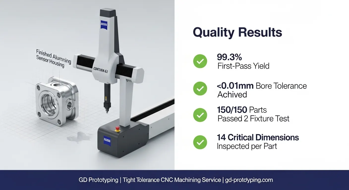
Every batch of 25 parts went to our Zeiss CONTURA G2 CMM for full dimensional reporting. The CMM program checked 14 dimensions per part, including:
- Central bore diameter (Ø22.000mm ±0.01mm)
- Bore cylindricity (max 0.005mm)
- Mating face flatness (max 0.01mm)
- True position of 4 M4 threaded holes (±0.05mm)
- Wall thickness at 3 cross-sections (min 1.2mm)
We also performed a 100% visual inspection for surface defects, anodize uniformity, and thread integrity. Thread gauges (Go/No-Go, M4 x 0.7) were used on all threaded holes.
Final CMM data was compiled into a FAI (First Article Inspection) report delivered with the shipment. You can learn more about GD Prototyping's inspection standards on our CNC machining services page.
Results
| Metric | Target | Achieved |
|---|---|---|
| Delivery time | 14 working days | 12 working days |
| First-pass yield | >95% | 99.3% (149/150 parts) |
| Bore diameter conformance | 100% within ±0.01mm | 100% |
| Anodize thickness | 15 μm ±2 μm | 14.8 μm avg |
| Client fixture fit test | Pass all 150 | 150/150 passed |
| Rejected parts | <5 | 1 (cosmetic scratch, remade) |
The client's engineering team confirmed that all 150 parts passed their engine test fixture on the first installation attempt. This was the first time their pre-production batch passed without rework since the project started 18 months earlier.
For more real-world results like this, browse our full library of CNC machining case studies.
Why CNC Machining Was the Right Choice
The client initially explored two alternatives before choosing CNC machining.
Investment casting was ruled out at this quantity. Tooling cost for a die cast mold starts at $8,000 to $15,000, and lead time for tooling alone is 4 to 6 weeks. For 150 validation parts, it doesn't make economic sense. Casting also can't guarantee ±0.01mm bore tolerance without secondary machining anyway.
Metal 3D printing (DMLS) was considered for its geometry flexibility. But DMLS parts in AlSi10Mg don't match the mechanical properties of wrought 6061-T6, especially fatigue resistance under cyclic pressure. DMLS also produces Ra 8 to 15 μm surfaces out of the machine, requiring heavy post-machining to reach Ra 0.8 μm on the bore.
CNC machining won because:
- It works directly with wrought 6061-T6, which meets the OEM's material specification
- It achieves ±0.01mm tolerance without secondary operations (when toolpath and fixturing are engineered correctly)
- It's cost-effective at 50 to 500 parts with no tooling investment
- Lead time is 10 to 15 days versus 6 to 10 weeks for cast alternatives
For precision part validation at low volume, tight tolerance CNC machining service is the most direct path from CAD to certified parts. GD Prototyping also offers CNC lathing for turned components and 5-axis CNC milling for complex geometries that require tight tolerances on multiple faces simultaneously.
FAQ
What is tight tolerance CNC machining?
Tight tolerance CNC machining refers to machining parts to dimensional accuracies tighter than standard ISO 2768-m (medium). In practice, this means holding tolerances of ±0.01mm to ±0.05mm. It requires precise fixturing, thermal management, tool path optimization, and CMM inspection to verify dimensions. Standard machining typically holds ±0.1mm to ±0.2mm.
What materials are best for tight tolerance CNC machining?
Aluminum 6061-T6 is one of the most machinable alloys and responds well to tight tolerance work when thermal expansion is managed. Stainless steel 316L, titanium Ti-6Al-4V, and engineering plastics like PEEK are also common. Material selection affects thermal expansion, tool wear rates, and achievable surface finish. Each material needs its own speeds, feeds, and tooling strategy.
How does anodizing affect tight tolerances on aluminum?
Type II anodize adds 15 μm to 20 μm per surface. For bores with ±0.01mm tolerance, this matters a great deal. The solution is to pre-machine the bore undersize by the expected anodize build-up, then re-bore after anodizing. Alternatively, mask the critical bore before anodizing. Always confirm anodize thickness with your supplier before finalizing drawing dimensions.
What is the minimum wall thickness for tight tolerance aluminum CNC parts?
For Aluminum 6061-T6, we routinely machine walls down to 0.8mm to 1.0mm on prototype runs. For production quantities above 50 parts, we recommend a minimum of 1.2mm for walls adjacent to tight tolerance bores. Thinner walls flex under cutting pressure, which makes holding ±0.01mm tolerances difficult without specialized fixturing. Our CNC machining case studies show further examples of thin-wall precision work.
How long does tight tolerance CNC machining take?
For parts like the sensor housing in this case study (87mm x 54mm x 32mm, 150 units), expect 10 to 14 working days from drawing approval to shipment. More complex geometries or harder materials like titanium can extend this to 15 to 20 days. Rush jobs with simplified geometry are sometimes achievable in 5 to 7 days. Contact GD Prototyping to get a project-specific timeline and quote.
Conclusion
Tight tolerance CNC machining is not just about buying a precise machine. It's about engineering every step: fixturing, thermal management, toolpath, in-process measurement, and post-process inspection. On this automotive sensor housing project, we held ±0.01mm bore tolerance across 150 aluminum parts and delivered 2 days early. That result came from process discipline, not luck.
If your next project has thin walls, tight bores, or critical fit requirements, we'd like to review your drawings. GD Prototyping supports projects from single prototypes to production runs of 1,000+ parts, with 5-axis CNC machining, CNC turning, and full CMM inspection in-house.
Request a free quote for your tight tolerance CNC part today.
