
Sink Marks in Injection Molding: Causes & Fixes
An engineer can spend months perfecting a product's design. Every curve and feature is meticulously planned. Yet, when the first parts come out of the injection mold, the design can be marred by unsightly surface depressions. These flaws are known as sink marks. They are the most common and frustrating cosmetic defect in injection molding. Sink marks can compromise the aesthetic appeal of a product. They can also indicate underlying structural issues within the part. Understanding the root cause of sink marks is the first step to eliminating them.
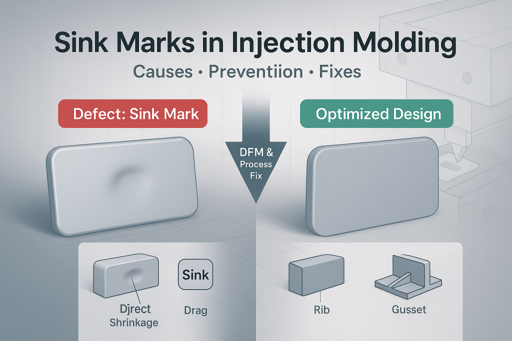
Sink marks are small craters or depressions on the surface of an injection molded part. They are caused by the non-uniform cooling and thermal shrinkage of the plastic, typically occurring in thick sections or on surfaces opposite features like ribs and bosses. Fortunately, sink marks are almost always preventable. They can be eliminated through intelligent part design and optimized process control.
As a leader in Design for Manufacturability (DFM), GD-Prototyping has helped thousands of clients diagnose and solve molding issues. Our experience shows that the most effective way to fix sink marks is to design them out of the part before the first piece of steel is ever cut for the mold. This guide provides a deep, technical dive into the science behind sink marks. We will detail every design and process-related cause and provide a comprehensive set of actionable solutions.
The Root Cause: Understanding the Science of Shrinkage
To eliminate sink marks, one must first understand the fundamental physics of why they form. The cause is not a mystery; it is a predictable outcome of how thermoplastic materials behave when they cool. Every sink mark can be traced back to one core principle: differential cooling and volumetric contraction.
The Volumetric Contraction of Thermoplastics
All thermoplastics, from common ABS to high-performance PEEK, shrink as they transition from a hot, molten liquid to a cool, solid state. This is a natural and unavoidable physical property. The material's density increases as it cools, causing its total volume to decrease. A professional mold designer and process engineer will account for this general shrinkage. They make the mold cavity slightly larger than the final desired part dimensions. This ensures the part is the correct size after it has fully cooled.
The Principle of Differential Cooling
The problem begins when different sections of a single part cool at different rates. The rate at which a section of plastic cools is directly proportional to its thickness. A thin wall section, with its large surface-area-to-volume ratio, can dissipate heat and solidify very quickly. A thick section, such as a solid boss or a heavy rib, has a much smaller surface-area-to-volume ratio. Its core remains insulated and stays molten for a much longer time.
This difference in cooling rates is called differential cooling. It is the primary antagonist in the battle against molding defects.
How Shrinkage Creates a Sink
The mechanism of sink mark formation is a direct result of this differential cooling.
- Molten plastic is injected into the mold cavity, filling the entire space.
- The cooling process begins. The outer surfaces of the part, which are in contact with the relatively cool steel walls of the mold, "freeze" and solidify first, forming a rigid skin.
- In a thin section, the entire wall solidifies quickly and uniformly.
- However, in a thick section, a large core of molten plastic remains trapped beneath the solidified outer skin.
- As this molten core finally cools and shrinks, it pulls inward on the still-soft outer skin.
- This pulling action causes the surface to collapse inward, creating the characteristic depression or crater known as a sink mark.
Design-Related Causes of Sink Marks
The vast majority of sink marks are not a molding problem; they are a design problem. The features that cause sink are literally designed into the 3D CAD model. A thorough DFM review is the most effective way to identify and eliminate these issues at the earliest possible stage. An experienced manufacturing partner can spot these potential problems and recommend simple design changes that will lead to a perfect, defect-free part.
How Does Part Design Create Sink Marks?
Non-Uniform Wall Thickness
This is the number one cause of sink marks and nearly all other molding defects. A part designed with both very thin and very thick sections is a recipe for differential cooling and internal stress. The thick sections will cool slower, shrink more, and cause sink marks on their surfaces. The "golden rule" of injection molding design is to maintain a consistent, uniform wall thickness throughout the entire part whenever possible.
Poorly Designed Ribs and Bosses
Ribs are added to a part to increase its strength and stiffness. Bosses are added to provide mounting points for screws. These features are essential, but if designed incorrectly, they are guaranteed to cause sink marks. The problem occurs when the base of the rib or boss is too thick relative to the nominal wall it is attached to. This creates a localized thick section, and a sink mark will appear on the opposite "show" surface. The industry-standard rule is that the thickness of a rib or boss wall should be no more than 40% to 60% of the nominal wall thickness.
Sharp Internal Corners
Sharp internal corners are another common source of sink marks. When two walls meet at a sharp 90-degree angle, the corner contains significantly more material than the adjacent walls. This corner becomes an unintended thick section. It will cool slower than the walls, and the resulting shrinkage will often cause a sink mark on the outside corner. To prevent this, all internal corners should have a generous radius. A good rule of thumb is that the inside radius should be at least 0.5 times the nominal wall thickness.
Proximity of Features
Even if individual ribs and bosses are designed correctly, placing them too close together can create a problem. A dense cluster of features can act as a single, large thick section. The heat from each feature combines, creating a hot spot in the mold that cools very slowly. This can lead to a large, flat sink mark in that area. Features should be spaced far enough apart to allow for uniform cooling.
Process-Related Causes of Sink Marks
While part design is the primary cause, even a perfectly designed part can exhibit sink marks if the injection molding process is not optimized. A skilled process engineer can adjust several key parameters on the machine to help mitigate or eliminate sink. These adjustments all focus on one goal: compensating for the material's natural shrinkage.
How Can the Molding Process Cause Sink Marks?
1. Insufficient Holding Pressure or Time
After the initial, high-speed injection fills the mold cavity, the machine transitions to a "packing" or "holding" phase. During this phase, pressure is maintained on the molten plastic for a set period. This holding pressure forces additional material into the cavity to compensate for the shrinkage that occurs as the part cools. If the holding pressure is too low, or if the holding time is too short, not enough extra material will be packed into the thick sections. This will result in a more severe sink mark.
2. Low Injection Pressure or Speed
The initial fill of the mold must be fast and powerful enough to pack out the cavity completely. If the injection pressure or speed is set too low, the plastic may begin to cool and solidify before the cavity is fully pressurized. This can lead to under-packed areas that are prone to sinking.
3. High Melt or Mold Temperature
Running the process too hot can exacerbate sink mark issues. A higher melt temperature means the plastic is less viscous and will shrink more as it cools. A higher mold temperature means the part will take longer to solidify. This longer cooling time gives the thick sections more time to shrink and pull the surface inward. Reducing the melt and mold temperatures (within the material's recommended processing window) can often help reduce sink.
4. Inadequate Gate Size or Location
The gate is the small opening through which the molten plastic enters the mold cavity. It is a critical feature that controls material flow. If the gate is too small, it can "freeze off" or solidify too early in the cycle. When this happens, the holding pressure from the machine is cut off from the part. It can no longer force additional material into the cavity to compensate for shrinkage, leading to severe sink. The location of the gate is also critical. It should be positioned to allow the thickest sections of the part to be filled and packed out effectively. The design of Injection Molding Gate Types has a direct impact on preventing sink marks.
A Comprehensive Guide to Fixing and Preventing Sink Marks
The best approach to sink marks is a proactive, two-pronged strategy. The first and most effective is through proper Design for Manufacturability (DFM). The second is through expert process optimization.
How Can Sink Marks Be Eliminated?
Solutions for the Part Designer (DFM)
These are the changes made to the 3D CAD model before the mold is built.
- Maintain Uniform Wall Thickness: Strive to keep the wall thickness consistent throughout the part.
- Core Out Thick Sections: Do not design solid sections. Hollow them out from a non-cosmetic side to create a uniform wall.
- Follow the 40-60% Rule for Ribs/Bosses: Ensure that any supporting feature is no more than 60% of the thickness of the wall it joins.
- Add Generous Radii: Add a radius to all internal corners that is at least half the nominal wall thickness.
- Use Gradual Transitions: If a change in thickness is unavoidable, use a gentle ramp or chamfer to transition between the two sections.
- Properly designed features must also include an adequate Draft Angle to ensure the part can be cleanly ejected from the mold.
Solutions for the Process Engineer
These are the adjustments made at the molding machine.
- Increase Holding Pressure and Time: This is the most effective process adjustment. It forces more material into the mold to offset shrinkage.
- Increase Shot Size: Ensure that the total volume of plastic being injected is sufficient to completely fill and pack the part.
- Decrease Melt and Mold Temperatures: Running cooler can reduce the total amount of shrinkage and help the part set up faster.
- Optimize Gate Location and Size: In some cases, the mold may need to be modified to enlarge the gate or move it to a more effective location.
The Ultimate Sink Mark Prevention Checklist and Before/After Examples
A proactive DFM review is the best insurance against cosmetic defects. Designers can use this simple checklist to audit their own parts before sending them for a quote.
A Proactive Checklist for Designers
- Is the nominal wall thickness consistent throughout the part?
- Have all unavoidable thick sections been cored out from a non-cosmetic side?
- Are all ribs designed to be no more than 60% of the nominal wall thickness?
- Are all bosses properly cored out and supported with gussets instead of thick bases?
- Are all internal corners designed with a radius of at least 50% of the wall thickness?
- Is the chosen material (e.g., a low-shrink grade) appropriate for the design's geometry?
Before and After Design Examples
[Image showing a "Before" design of a part with a solid boss, and an "After" design of the same part with a properly cored-out and gusseted boss.]
Before: A part is designed with a thick, solid boss for a screw. This design is guaranteed to create a large sink mark on the cosmetic surface opposite the boss.
After: The same part is redesigned using DFM principles. The solid boss is "cored out," creating a feature with a uniform wall thickness. Thin support gussets are added to provide the necessary strength. This design will produce a structurally sound and cosmetically perfect part with no sink marks.
Conclusion
Sink marks are a common but preventable defect in injection molding. They are a direct and predictable result of the laws of thermodynamics. While a skilled process engineer can make adjustments at the press to minimize them, the most effective and economical solution is to address the root cause during the part design phase. By adhering to the principles of uniform wall thickness and proper feature design, engineers can create robust, functional, and aesthetically pleasing parts.
This commitment to Design for Manufacturability is the key to a successful project. At GD-Prototyping, our team of experienced engineers provides expert DFM feedback with every quote. We help our clients identify and correct potential issues like sink marks before they become costly problems.