
A Guide to Sheet Metal Tolerances (ISO 2768)
In the world of precision engineering, communication is everything. A designer in one location must be able to communicate their exact requirements for a part to a fabricator in another. This communication must be clear, concise, and universally understood. For the physical dimensions of a part, this language is tolerance. To ensure everyone is speaking the same language, international standards were created. One of the most important and widely used of these standards is ISO 2768.
ISO 2768 is an international standard that provides a simplified system of general tolerances for linear, angular, and geometrical dimensions. It is used on engineering drawings to define a default, acceptable level of precision for all features that do not have a specific, individual tolerance applied to them. Understanding this standard is essential for any engineer or designer working with sheet metal fabrication.
As a precision fabrication shop that works with clients globally, GD-Prototyping adheres to ISO 2768 standards daily. It is the foundation of our commitment to quality and consistency. This guide provides a comprehensive overview of the standard. We will explain how it works, how its different classes are applied, and how it specifically relates to the nuances of the sheet metal manufacturing process.
The Purpose of General Tolerances and ISO 2768
Imagine a complex sheet metal enclosure with dozens of bends, holes, and slots. It would be impractical and visually cluttered to apply a specific tolerance to every single dimension on the engineering drawing. This would make the drawing difficult to read and would require an excessive amount of inspection time.
Why is a General Tolerance Standard Needed?
This is where a general tolerance standard like ISO 2768 becomes invaluable. Instead of tolerancing every feature individually, a designer can add a single note to the drawing's title block. This note, such as "ISO 2768-mK," automatically applies a default set of tolerances to all features on the part. This simplifies the drawing and clearly communicates a baseline level of expected quality and precision.
It provides a common, internationally recognized language for precision. It ensures that both the designer and the fabricator are working to the same set of expectations, even before the first piece of metal is cut.
The Two Parts of the Standard
The ISO 2768 standard is divided into two distinct parts. They are almost always used together.
- ISO 2768-1: This part covers general tolerances for linear and angular dimensions. It controls the "size" of features.
- ISO 2768-2: This part covers general geometrical tolerances. It controls the "form" or "shape" of features, such as their straightness, flatness, and perpendicularity.
A complete specification in a drawing's title block will reference both parts, for example, "ISO 2768-mK." The "m" refers to the tolerance class from Part 1, and the "K" refers to the tolerance class from Part 2.
A Deep Dive into ISO 2768-1: Linear and Angular Tolerances
ISO 2768-1 is the first part of the standard. It provides a framework for controlling the basic size of features. It recognizes that different applications require different levels of precision. Therefore, it defines four distinct tolerance classes.
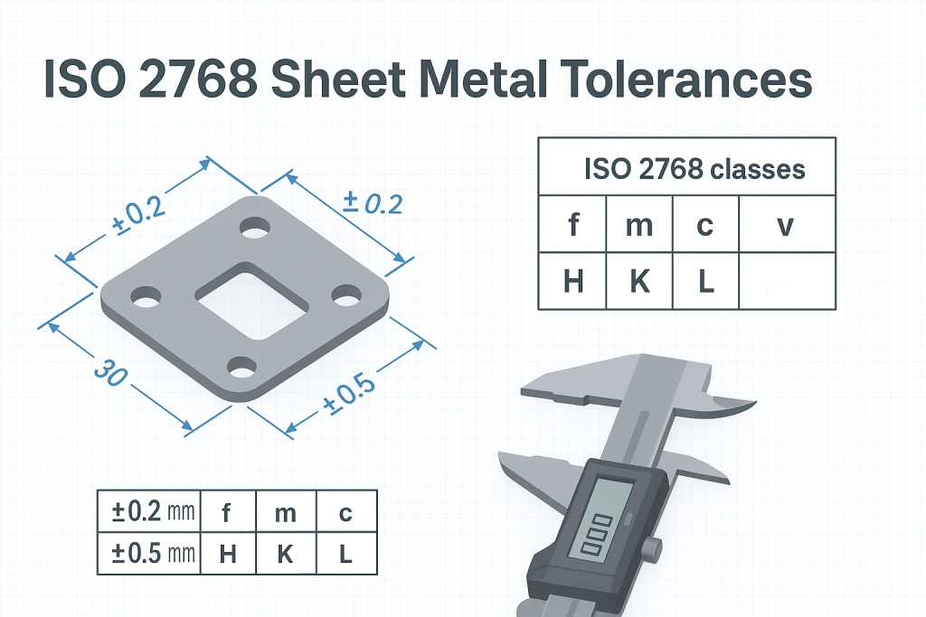
The Four Tolerance Classes (f, m, c, v)
A designer chooses a class based on the functional requirements of the part.
- f (fine): This class is used for high-precision components where a very tight control over dimensions is required.
- m (medium): This is the most common and widely used class. It provides a good balance of precision and manufacturability and is suitable for the vast majority of general fabrication applications.
- c (coarse): This class is used for parts where a lower level of precision is acceptable and large dimensional variations will not affect the part's function.
- v (very coarse): This is the least restrictive class, used for non-critical dimensions on parts like rough castings or forgings where precision is not a primary concern.
The Reference Table for Linear Dimensions (ISO 2768-1)
This table defines the permissible deviations in millimeters (mm) for different nominal length ranges.
| Nominal Length Range (mm) | Class f (fine) | Class m (medium) | Class c (coarse) | Class v (very coarse) |
| 0.5 up to 3 | ±0.05 | ±0.1 | ±0.2 | - |
| > 3 up to 6 | ±0.05 | ±0.1 | ±0.3 | ±0.5 |
| > 6 up to 30 | ±0.1 | ±0.2 | ±0.5 | ±1.0 |
| > 30 up to 120 | ±0.15 | ±0.3 | ±0.8 | ±1.5 |
| > 120 up to 400 | ±0.2 | ±0.5 | ±1.2 | ±2.5 |
| > 400 up to 1000 | ±0.3 | ±0.8 | ±2.0 | ±4.0 |
| > 1000 up to 2000 | ±0.5 | ±1.2 | ±3.0 | ±6.0 |
| > 2000 up to 4000 | ±0.8 | ±2.0 | ±4.0 | ±8.0 |
The Reference Table for Angular Dimensions (ISO 2768-1)
This table defines the permissible deviations for angles, based on the length of the shorter leg of the angle in question. The values are given in degrees and arcminutes (60 arcminutes = 1 degree).
| Nominal Length of Shorter Leg (mm) | Class f (fine) | Class m (medium) | Class c (coarse) | Class v (very coarse) |
| up to 10 | ±1° | ±1° | ±1° 30' | ±3° |
| > 10 up to 50 | ±30' | ±30' | ±1° | ±2° |
| > 50 up to 120 | ±20' | ±20' | ±30' | ±1° |
| > 120 up to 400 | ±10' | ±10' | ±15' | ±30' |
| > 400 | ±5' | ±5' | ±10' | ±20' |
A Deep Dive into ISO 2768-2: Geometrical Tolerances
ISO 2768-2 builds upon the foundation of Part 1. It recognizes that controlling a feature's size is not enough. The feature's shape and its relationship to other features are also critical. This part of the standard controls the "form" of a part.
The Three Tolerance Classes (H, K, L)
Similar to Part 1, this part of the standard provides three classes of precision.
- H (fine): For high-precision applications.
- K (medium): A common, general-purpose class.
- L (coarse): For applications where geometric form is less critical.
The Reference Table for Geometrical Tolerances (ISO 2768-2)
This table defines the permissible deviations for straightness, flatness, perpendicularity, symmetry, and circular run-out. The tolerance value is determined by the nominal length of the feature being controlled.
| Nominal Length Range (mm) | Class H (fine) | Class K (medium) | Class L (coarse) |
| up to 10 | 0.02 | 0.05 | 0.1 |
| > 10 up to 30 | 0.05 | 0.1 | 0.2 |
| > 30 up to 100 | 0.1 | 0.2 | 0.4 |
| > 100 up to 300 | 0.2 | 0.4 | 0.8 |
| > 300 up to 1000 | 0.3 | 0.6 | 1.2 |
| > 1000 up to 3000 | 0.4 | 0.8 | 1.6 |
Perpendicularity (in mm)
| Nominal Length of Shorter Side (mm) | Class H | Class K | Class L |
| up to 100 | 0.2 | 0.4 | 0.6 |
| > 100 up to 300 | 0.3 | 0.6 | 1.0 |
| > 300 up to 1000 | 0.4 | 0.8 | 1.5 |
| > 1000 up to 3000 | 0.5 | 1.0 | 2.0 |
Applying ISO 2768 Specifically to Sheet Metal Fabrication
It is crucial to understand that ISO 2768 is a general standard. Therefore, its application to sheet metal requires an understanding of the unique characteristics of the fabrication process.
The "Medium" Class as the Industry Standard
For the vast majority of sheet metal components, the standard specification is ISO 2768-mK.
- The "m" (medium) class from Part 1 provides a level of linear precision that is realistically and economically achievable with modern laser cutting and press brake equipment.
- The "K" (medium) class from Part 2 provides a good general control over the flatness and perpendicularity of features after bending.
Requesting a tighter class, such as "fH," for a general sheet metal part is often impractical. It can dramatically increase the cost due to the need for special handling, slower processing, and a much higher inspection burden.
How Fabrication Processes Affect Achievable Tolerances
The final tolerance of a sheet metal part is a result of the tolerances of each step in its manufacturing process.
- Laser Cutting / Punching: The initial 2D flat pattern can be cut with very high precision. A modern fiber laser can often hold tolerances that are well within the "f" (fine) class.
- Bending (Press Brake): This is the stage that introduces the most variation. The process of bending metal on a press brake is subject to variations in material thickness, hardness, and grain direction. This results in small variations in the final angle and flange dimensions. It is this bending variation that makes the "m" (medium) class the most appropriate overall standard.
When to Deviate from the General Tolerance
The purpose of a general tolerance is to cover non-critical features. If a specific feature on your part is critical for its function, it must be given a specific, tighter tolerance. For example, the pattern of mounting holes that must align with another part, or the overall width of an enclosure that must fit into a specific space. When a specific tolerance is called out on a dimension, it always overrides the general tolerance in the title block. Understanding these principles is a key part of our Sheet Metal Design Guidelines.
Factors Influencing Real-World Sheet Metal Tolerances
Even when working to a standard like ISO 2768, several real-world factors can influence the final precision of a sheet metal part. An expert fabricator understands and manages these variables.
What Other Factors Affect Precision?
- Material Type and Thickness: Different materials behave differently. For example, stainless steel has more "springback" after bending than mild steel, which can affect the final angle. Thicker materials are also generally harder to bend to a tight angular tolerance than thinner materials.
- Bend Radius and Proximity to Features: A very tight bend radius can introduce more stress and potential deviation. Holes or other features located too close to a bend can become distorted, affecting their positional tolerance.
- Complexity of the Part: A part with many bends in different directions has more opportunities for cumulative error to build up. A simple bracket will be easier to hold to a tight tolerance than a complex, multi-bend chassis.
- Machine and Tooling Condition: The precision of the final part is directly related to the quality of the machines used to make it. A well-maintained, modern press brake with high-quality tooling will produce much more consistent and accurate parts than older equipment.
These variations can add up in an assembly. This is why a Tolerance Stack-Up Analysis is often necessary for complex products with many interacting components.
Conclusion
ISO 2768 is a powerful and essential tool in modern manufacturing. It creates a universal language for communicating an expected level of quality and precision for sheet metal parts. By using this standard, designers can simplify their drawings and ensure that their design intent is clearly understood by the fabricator.
Choosing the appropriate tolerance class—most often "mK" for sheet metal—is key to creating a part that is both functional and economical to produce. Understanding how the fabrication process itself influences these general tolerances allows for a more intelligent and collaborative design process. At GD-Prototyping, our commitment to precision and our adherence to international standards like ISO 2768 ensure that our clients receive the highest quality parts every time.