
Robotics CNC Machining Parts: Tolerances, Materials, and How to Order
Robotics CNC machining parts are precision-machined aluminum, stainless steel, or titanium components used in robot arms, joints, end effectors, and frames. CNC machining achieves tolerances of ±0.01mm to ±0.05mm, which is required for servo motor mounts, bearing housings, and harmonic drive interfaces. At GD Prototyping, we produce robotics parts in 7 to 15 days with full CMM inspection and material certifications included.
What Are Robotics CNC Machining Parts?
Robotics CNC machining parts are structural and functional components manufactured by removing material from a billet using computer-controlled cutting tools. These parts go directly into industrial robots, collaborative robot arms (cobots), surgical robots, and autonomous mobile robots (AMRs).
CNC machining is the preferred process for robotic parts because robots demand tight tolerances that casting and 3D printing can't consistently deliver. A 0.05mm bore error on a joint housing causes positional drift in the robot arm. That drift compounds across each axis and creates repeatable positioning errors that shut down automated lines.
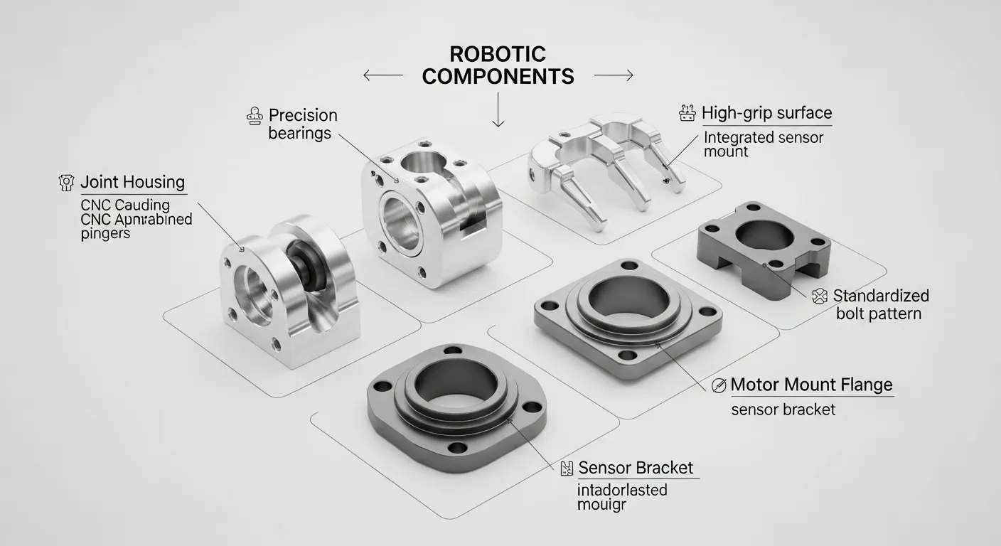
The most common robotics parts we machine include:
- Joint housings and axis link bodies
- Harmonic drive and gearbox mounting flanges
- Servo motor mount plates
- Gripper fingers and end-of-arm tooling (EOAT)
- Ball screw support brackets
- Encoder and sensor housings
- Base frames and column mounts
- Camera and vision system brackets
What Tolerances Are Achievable for Robotics Parts?
CNC machining tolerances for robotics parts range from ±0.005mm to ±0.05mm depending on the feature type and machine setup. Here's what to expect:
| Feature Type | Achievable Tolerance | Typical Process |
|---|---|---|
| Precision bore diameter | ±0.005mm to ±0.010mm | Single-point boring bar |
| Bore coaxiality | 0.008mm to 0.015mm | 5-axis + on-machine probing |
| Mating face flatness | 0.005mm to 0.015mm | High-feed face milling |
| General profile dimensions | ±0.02mm to ±0.05mm | 3-axis or 5-axis milling |
| Thread accuracy | 6H/6g standard | CNC tapping or thread milling |
| Positional tolerance | ±0.01mm to ±0.02mm | Zero-point clamping system |
For robotic joint housings, the critical tolerance is bore coaxiality. The motor-side bore and output-side bore must be coaxial within 0.015mm over the part length. We achieve this using a Renishaw OMP60 on-machine probing system that measures and corrects datum offset before every finishing cycle.
Our standard machining tolerance at GD Prototyping's CNC machining service is ±0.05mm. For robotics applications requiring tighter specs, we work from your inspection plan and hold tolerances down to ±0.005mm on bores.
Best Materials for Robotics CNC Machining Parts
Material selection directly affects part weight, strength, corrosion resistance, and machinability. Here are the most common choices:
Aluminum 6061-T6
The most widely used material for robotic structural parts. It has a tensile strength of 310 MPa, excellent machinability, and accepts hard anodize (Type III) for wear resistance. It's the right choice for joint housings, link bodies, and mounting plates where weight and rigidity are both priorities.
Aluminum 7075-T6
Stronger than 6061 at 572 MPa tensile strength, but slightly harder to machine. We use 7075-T6 for high-stress parts like gripper fingers, end effectors, and parts with thin walls under heavy cyclic load. It also anodizes well, though the finish is slightly less uniform than 6061.
Stainless Steel 316L
Used for surgical robots, food-handling robots, and any environment with chemical exposure or high humidity. It's heavier than aluminum but offers excellent corrosion resistance and biocompatibility. Machining 316L requires lower speeds and rigid fixturing to avoid work hardening.
Titanium Grade 5 (Ti-6Al-4V)
Used in aerospace robotics and medical surgical robots where both extreme strength and low weight are required. We machine Ti-6Al-4V with titanium-specific toolpaths and cutting parameters. It's the most expensive material option but delivers the best strength-to-weight ratio available.
Peek and Engineering Plastics
For non-structural parts like cable guides, sensor covers, and lightweight brackets, PEEK and Delrin (POM) are excellent CNC-machinable options. They're electrically non-conductive and chemically resistant, useful in electronics assembly robots.
You can review the full material list available for your robotics project on our CNC machining cases and materials page.
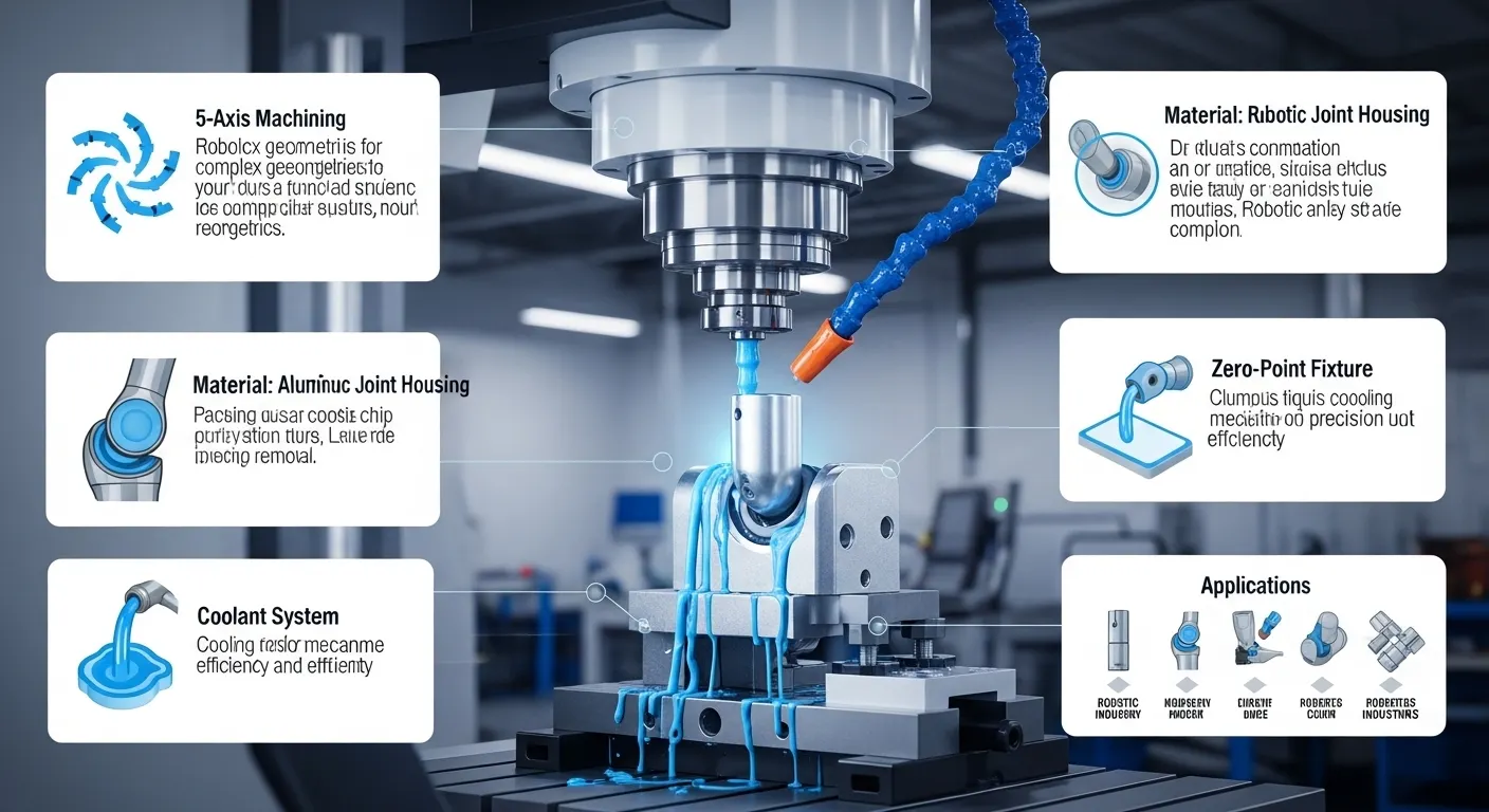
5-Axis vs 3-Axis CNC for Robotics Parts
Most robotics components require 5-axis CNC machining. Here's why it matters:
3-axis CNC can only cut along X, Y, and Z. Complex robotics parts with angled bores, curved surfaces, undercuts, or multi-face features need multiple setups. Each re-clamping introduces datum shift, which accumulates tolerance error across the part.
5-axis CNC tilts the spindle and rotates the table, cutting complex geometry in a single setup. This eliminates re-clamping error and keeps coaxiality and positional tolerances tight. For joint housings with bores on two or more faces, 5-axis is the only way to hold ±0.02mm coaxiality reliably.
At GD Prototyping, our DMG Mori DMU 65 monoBLOCK handles full 5-axis simultaneous machining for the most complex robotic geometries. For simpler parts like flat mounting plates or sensor brackets, our 3-axis Haas VF-2 handles production runs efficiently at lower cost.
Key Challenges in Machining Robotics Parts
Thin-Wall Deformation
Gripper fingers and link bodies often have walls under 2mm. Cutting force during milling pushes the wall, causing dimensional bow and surface finish failure. We solve this with:
- Machinable wax fill-support for walls under 1.8mm
- Climb-milling-only toolpaths to reduce lateral cutting force
- Maximum 0.15mm radial depth of cut on finishing passes
Deep Pocket and Bore Accuracy
Harmonic drive interfaces on joint housings require deep pockets (30mm to 40mm) and precision bores in the same setup. Long-reach tools cause chatter. We use shrink-fit tool holders with minimal gauge length to reduce runout below 0.003mm, which keeps surface finish and bore accuracy in spec.
Thermal Expansion During Machining
Aluminum expands during cutting. At high spindle speeds, a 148mm aluminum part can grow 0.015mm from heat alone. We use through-tool coolant at 60 bar and machine critical bores at the end of the cycle after thermal stabilization, not at the beginning.
Surface Finishing Options for Robotics Parts
CNC-machined robotic parts almost always need a surface finish for wear resistance, corrosion protection, or aesthetics:
- Hard Anodize Type III: 25µm coating, hardness up to 70 HRC surface, ideal for joint housings and gripper fingers under friction and wear
- Clear Anodize Type II: 12µm coating, cosmetic protection for external visible parts
- Electroless Nickel Plating: Used on stainless steel or aluminum where uniform coating thickness is critical for press-fit bores
- Bead Blasting: Uniform matte finish, often applied before anodizing for consistent cosmetic appearance
- Passivation: For stainless steel parts in surgical or food-handling robots, per ASTM A967
Quality Control and Inspection
Every robotics part we produce goes through a structured inspection process before shipment:
- Pre-CMM dimensional check with digital calipers on all features
- CMM inspection on a Zeiss Contura G2 RDS for all critical dimensions per your inspection plan
- Surface roughness measurement with a contact profilometer
- Functional gauge check for bore fits and thread gauging
- Visual inspection under magnification for burrs, surface defects, and edge breaks
We provide a Certificate of Conformance (CoC) and First Article Inspection (FAI) report with every order. Material traceability documents (mill certifications per ASTM B209 for aluminum) are included on request. Our quality process aligns with ISO 9001 standards.
Why Choose CNC Machining Over Casting or 3D Printing for Robotic Parts?
Buyers often ask whether die casting or metal 3D printing can replace CNC machining for robotics components. Here's the honest comparison:
| Factor | CNC Machining | Die Casting | Metal 3D Printing |
|---|---|---|---|
| Bore tolerance | ±0.005mm | Requires secondary machining | ±0.1mm minimum |
| Material integrity | Full wrought alloy properties | Porosity risk at bores | Anisotropic, layer-dependent |
| Lead time (under 200 pcs) | 7 to 15 days | 4 to 6 weeks (tooling) | 5 to 10 days |
| Cost at low volume | Moderate | High (tooling amortized) | High per-part cost |
| Surface finish | Ra 0.4 to 1.6 µm | Ra 1.6 to 6.3 µm as-cast | Ra 6.3 to 25 µm as-printed |
| Design flexibility | Full (no tooling) | Limited by draft angles | Full |
For batches under 500 parts with tight bore tolerances, CNC machining wins on every dimension that matters to a robotics engineer: accuracy, lead time, and structural integrity.
How to Order Robotics CNC Machining Parts at GD Prototyping
Ordering is straightforward. Here's the process:
- Upload your STEP or IGES files via our online quote form
- Specify material, tolerance, surface finish, and quantity in the request
- Receive a DFM (Design for Manufacturability) review and quote within 24 hours
- Approve the quote and PO — machining starts the same day
- Receive CMM report, CoC, and shipment tracking with your delivery
We work with robotics teams across Germany, the USA, Japan, and South Korea. Standard lead time for aluminum robotic parts is 7 to 15 business days. Rush 5-day service is available for simpler geometries and quantities under 50 pieces.
Get a free quote for your robotics CNC machining parts at GD Prototyping.
FAQ
What is the minimum wall thickness GD Prototyping can machine for robotic parts?
We reliably machine walls down to 0.8mm on aluminum using machinable wax support and vibration-damping toolpaths. For stainless steel, our practical minimum is 1.2mm. Thinner than these values requires a design review before quoting.
Can you machine robotic parts from customer-supplied material?
Yes. We accept customer-supplied billet stock with a valid mill certificate. We confirm the material spec before cutting. This is common for aerospace robotics applications where material traceability must be maintained from the source.
Do you offer prototypes before production runs?
Yes. We regularly run 5 to 10 prototype parts before full production for new robotic part designs. The prototype run lets your engineering team validate fit and function before committing to the full batch. Prototype lead time is typically 5 to 7 days. See our CNC machining prototype cases for examples.
What file formats do you accept for robotics CNC machining parts?
We accept STEP, IGES, STP, X_T (Parasolid), and DWG/DXF for 2D drawings. STEP files are preferred because they carry full 3D geometry and GD&T annotations. PDF drawings with dimension callouts are required alongside STEP files for tolerance-critical parts.
What industries do you serve for robotics CNC parts?
We serve industrial automation, automotive assembly robotics, medical and surgical robotics, electronics manufacturing robots, aerospace ground handling automation, and agricultural robotics. All orders include documentation suitable for regulated industries.
Start Your Robotics Parts Order Today
If you're sourcing precision robotic components and need a supplier who understands tight bore tolerances, thin-wall deformation risks, and fast delivery, GD Prototyping is ready to review your drawings today.
Upload your STEP files and get a quote and DFM review within 24 hours — no commitment required.