
Rapid Prototyping Services (2026): From CAD To Parts In 48H
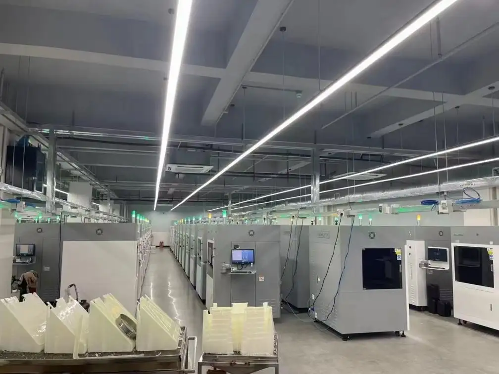
Rapid Prototyping Services are the fast way to turn a CAD file into a real, testable part—often within 48 hours in GD Prototyping—so your team can learn early, fix issues sooner, and move to production with more confidence. We run an advanced 3D printing center built for speed and repeatability, using proven technologies like SLA, SLS, MJF, and DMLS to support both plastic and metal projects. This 2026 beginner-friendly guide explains how the "CAD-to-parts" workflow works, what each process is best at, and how to choose materials, accuracy, and finishing without getting lost in jargon.
What "48H From CAD to Parts" Really Means in 2026
When people hear "48 hours," they often imagine printing starts the moment they click upload. In real Rapid Prototyping Services, the clock includes three practical steps: file review, process selection, and build planning. If your CAD is clean and the part fits a standard build setup, you can move extremely fast. If the model has thin walls, tight tolerance zones, or unclear functional surfaces, a short engineering review will usually save you a longer redesign later.
At GD Prototyping, we focus on making the first build meaningful, not just quick. For beginners, the most important mindset shift is this: your first prototype is not the finish line. It is a learning tool that reduces uncertainty.
• A "fast prototype" is valuable only if it tests the right risk (fit, strength, heat, assembly, or appearance).
• The fastest timeline comes from clear requirements, not from rushing the file.
Choose the Right 3D Printing Process for Your Prototype
Different Rapid Prototyping Services exist because not every part needs the same surface quality, strength, or heat resistance. Here is a simple way to match the process to your goal.
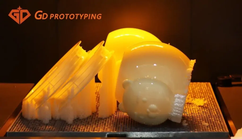
SLA relies on UV laser exposure to cure resin and form layers. It’s suited to high-resolution detail and smooth surfaces—visual prototypes, display models, dental models, or small features that need clean edges.
SLS fuses nylon powder layer by layer and typically does not require supports. It is a strong option for functional parts with complex shapes, internal channels, and durable performance.
MJF (Multi Jet Fusion) is excellent for strong, dimensionally stable plastic parts, especially when you need multiple pieces for functional testing or low-volume production. It is often selected for nylon parts where you want reliable strength and consistent results.
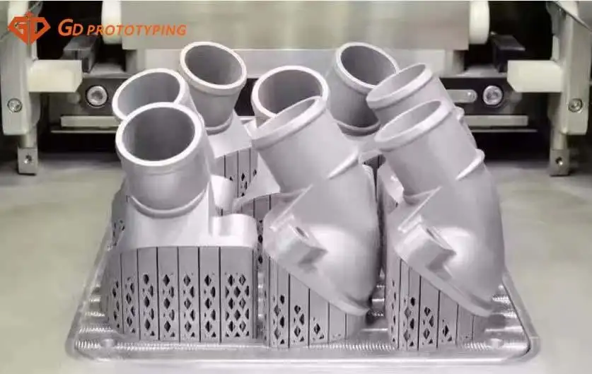
DMLS (Direct Metal Laser Sintering) builds dense metal parts using metal powders. It is used when plastic is not representative—such as metal brackets, industrial components, or parts that must survive mechanical and thermal loads.
• If you want a "realistic look & feel," start with SLA for appearance prototypes.
• If you need durable plastic performance, consider SLS or MJF for functional testing.
• If you need metal strength, move to DMLS for true metal behavior.
Learn the Practical Accuracy Numbers That Matter Most
Beginners often ask: "How accurate is 3D printing?" The better question is: "How accurate do I need to be for this test?" Your prototype should be accurate enough to validate fit and function, but not over-specified in a way that slows the project.
Here are real reference points we use in Rapid Prototyping Services planning:
SLA dimensional accuracy is typically +0.5% with a lower limit of +0.15 mm, with layer heights around 50–100 μm.
SLS and MJF are typically +0.3% with a lower limit of ±0.3 mm, with 80 μm layer height.
DMLS is commonly ±0.2 mm for features under 10 mm, and tighter planning is needed for critical interfaces; typical layer height can be around 30 μm.
These numbers are not just "specs." They help you decide where to place tolerance-critical features. If your design has one surface that must mate to another part, isolate that area, and avoid forcing the whole prototype to carry extreme tolerance requirements.
• Mark "critical surfaces" in your drawing notes to guide process choice and inspection focus.
• For assembly checks, design in practical clearances instead of fighting the process limits.
Pick Materials Like a Product Engineer, Not a Catalog Reader
A wide material range is only useful if it helps you simulate your real end-use conditions. At GD Prototyping, our Rapid Prototyping Services cover common plastics and engineering materials—such as ABS, PC, PP, Nylon (PA6/PA66), POM, PMMA, PEEK, PTFE—as well as metals like aluminum alloys, copper, brass, titanium, and more.
If you are new to material selection, start with the question: What do I need to learn from this prototype? Then choose the "closest practical match."
• For toughness and everyday durability tests, ABS-like options are a common starting point.
• For strength-to-weight considerations, aluminum alloys are often used in metal prototyping.
• For heat or chemical resistance exploration, PEEK/PTFE may be relevant—but only if your prototype test truly needs it.
Material choice also affects post-processing options, surface feel, and real-world durability. A prototype that survives handling and repeated assembly gives you better feedback than a fragile model that breaks before you learn anything.
Use Finishing Options to Make Prototypes More Realistic
A prototype should communicate clearly. Sometimes that is about function, and sometimes it is about presentation. Finishing is how Rapid Prototyping Services bridge the gap between "printed part" and "product-like part."
At GD Prototyping, common finishing options include:
• Standard Finish for clean parts with supports removed.
• Painting to simulate final color, gloss, and texture.
• Polishing for smoother surfaces and better appearance.
• Dyeing for nylon parts (often SLS/MJF) to achieve uniform color.
• Vapor Smoothing to reduce layer lines on certain plastics for a more consumer-ready surface.
• Bead Blasting for a uniform matte texture on plastics or metals.
• Heat Treatment for metal printed parts when strength and durability improvements matter.
Use finishing strategically. If you are testing ergonomics or a customer-facing look, finishing is not "cosmetic"—it is part of the evaluation.
A Simple CAD-to-Parts Checklist and a Clear CTA
When speed is the priority, the best Rapid Prototyping Services projects follow a predictable checklist. This avoids back-and-forth and reduces the risk of "fast but wrong" prototypes.
• Share your CAD format and confirm the part’s goal (visual, fit-check, functional, or metal strength).
• Identify critical interfaces (holes, mating faces, snap fits) and your expected clearance needs.
• Choose one process first (SLA/SLS/MJF/DMLS) based on what you want to learn.
• Decide whether you need a basic surface or a product-like finish (painting, polishing, dyeing).
• If you need scaling later, note expected quantities for small-batch production planning.
CTA (Call-to-Action): If fast iteration is critical, send GD Prototyping your CAD, target material (plastic or metal), and the test you need. We’ll pick the right path—SLA, SLS, MJF, or DMLS—clarify accuracy limits, and deliver a no-nonsense quote to keep you iterating in 48 hours.