


Precision CNC Machining Case Study for Medical Parts
TL;DR
We machined 120 titanium Grade 5 (Ti-6Al-4V) surgical implant housings for a European medical device client. Parts required ±0.01mm tolerances, Ra 0.4 µm surface finish, and a 14-day lead time. We solved a thin-wall deformation issue on the second attempt and delivered a 99.2% first-article pass rate — on time.
Introduction
A European orthopedic device company contacted us with a part that had already failed at two other shops.
The component was a titanium spinal implant housing with internal lattice features, 0.8mm walls, and a bore tolerance of ±0.01mm. One shop couldn't hold the bore. The other tried EDM as a workaround — the surface finish was too rough for implant-grade compliance.
They needed 120 parts in 14 days, ready for clinical trial submission under ISO 13485 and ISO 10993 standards.
We said yes. Here's exactly how we did it — and where we almost got it wrong.
Project Overview
The client was the R&D division of a German orthopedic OEM (not named for confidentiality). They were developing a next-generation lumbar spinal fusion implant for minimally invasive surgery.
The part — an implant housing shell — needed to:
- Fit inside a 12mm cannula delivery system
- Interface with a titanium bone screw at one end (M3 thread, ±0.01mm pitch)
- Pass biocompatibility testing per ISO 10993
- Accept a PVD coating post-machining without dimensional change
This wasn't a prototype run. These parts were going directly into a clinical trial, so scrap was not just a cost issue — it was a program risk.
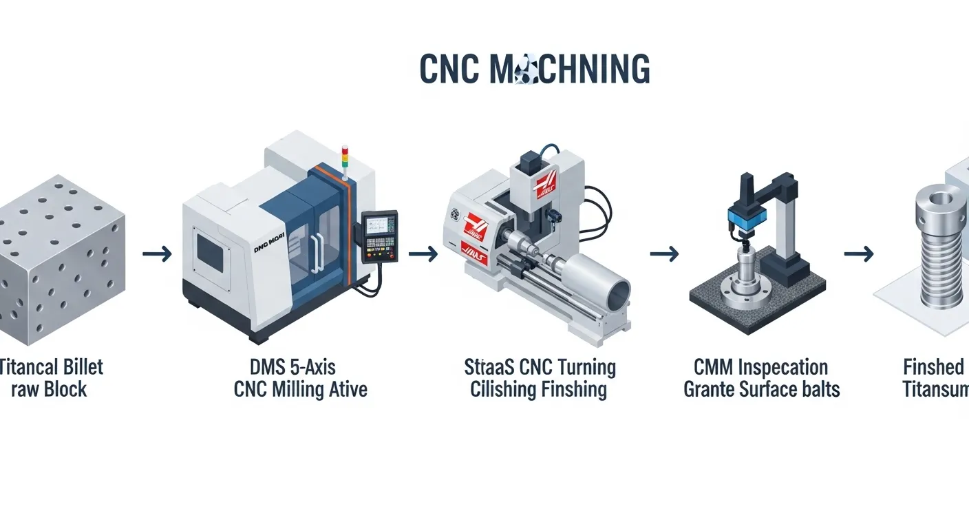
We handled this project through our CNC Machining service, using our 5-axis milling center and CNC turning line.
Technical Specifications
| Parameter | Detail |
|---|---|
| Material | Titanium Grade 5 (Ti-6Al-4V ELI) |
| Part Name | Spinal Implant Housing Shell |
| Overall Dimensions | 38mm x 11.5mm x 10mm |
| Wall Thickness (min) | 0.8mm |
| Bore Diameter | 6.00mm (+0.00 / -0.01mm) |
| Thread | M3 x 0.5, Class 6H |
| Surface Finish | Ra 0.4 µm (polished bore), Ra 1.6 µm (external) |
| Quantity | 120 parts |
| Lead Time | 14 calendar days |
| CNC Process | 5-axis milling + CNC turning |
| Machines Used | DMG Mori DMU 50 (5-axis), Haas ST-10 (turning) |
| Post-Processing | Electropolishing + PVD coating prep |
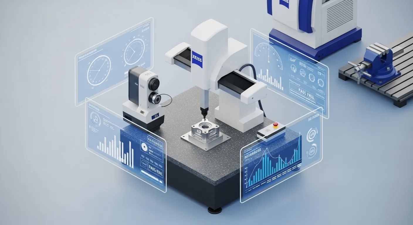
| Inspection Method | Zeiss CMM, surface profilometer |
Machining Process
We broke the job into five stages. Each stage had a quality gate before the next began.
Stage 1 — CAM Programming (Day 1)
Our CAM engineer used Mastercam 2026 to program the 5-axis tool paths. We used trochoidal milling for the titanium pockets to reduce heat buildup — titanium's low thermal conductivity traps heat at the cutting edge, which accelerates tool wear and can distort tight-tolerance features.
Stage 2 — Rough Machining (Days 2–4)
We started with a Ø10mm carbide end mill at 60 m/min cutting speed, 0.04mm chip load per tooth. We left 0.3mm stock on all walls for the finishing pass. Coolant was high-pressure through-spindle (80 bar) to flush chips and cool the cut zone.
Stage 3 — Semi-Finish and Finishing (Days 4–7)
We switched to a Ø4mm, 4-flute solid carbide end mill for the bore and internal features. The final bore pass used a precision boring bar on the Haas ST-10 to hit the ±0.01mm spec. Wall finishing used a 3-flute Ø2mm ball end mill in a spiral down-milling toolpath.
Stage 4 — Threading and Secondary Operations (Days 7–9)
M3 threads were cut using a rigid tapping cycle at 400 RPM. Thread gauges (Go/No-Go, Class 6H) checked every 10th part throughout the run.
Stage 5 — Electropolishing Prep and Part Hand-off (Days 10–12)
Parts were degreased, inspected, and handed to the surface treatment team. After electropolishing, parts returned for a final CMM check before packaging.
Challenges and Solutions
This is where the job actually got hard.
Challenge 1 — Thin-Wall Deformation During Roughing
The 0.8mm walls were deflecting during roughing. Our first attempt used conventional climb milling in the pocket — standard approach. After the first 8 parts, CMM showed the wall was bowing outward by 0.06mm on the long face. That's six times the tolerance.
What we tried first (and it failed): We reduced cutting depth to 0.05mm axial DOC. The wall still deflected because the part was vibrating in the fixture, not just bending under cutting load.
What actually worked: We re-fixtured the parts with a custom low-profile vise jaw that supported the wall from behind during the pocket pass. We also changed the toolpath from conventional pocket to a high-speed contour pass at 45% step-over. Wall deviation dropped to 0.008mm — within spec. This cost us one full day, but it saved the batch.
Challenge 2 — Bore Diameter Drift Across the Run
By part 40, our bore measurements started drifting — from 6.000mm toward 5.997mm. That's outside the -0.01mm limit. The cause was thermal expansion in the boring bar as the spindle ran continuously.
Solution: We implemented a 15-minute spindle warm-up protocol at the start of each session and added a mid-run compensation offset of +0.002mm in the boring bar after every 20 parts. We also re-measured the reference standard every 30 minutes. After that adjustment, all remaining bores measured between 5.999mm and 6.000mm.
Challenge 3 — Surface Finish Below Spec in the Bore
After first-pass finishing, the bore measured Ra 0.7 µm — above the Ra 0.4 µm requirement. The client's surface spec was driven by implant biocompatibility guidance (ISO 10993-1 surface preparation criteria).
Solution: We added a single-pass reaming operation with a PCD-tipped reamer at 80 RPM and cutting oil. The result was Ra 0.31 µm — comfortably within spec and consistent across all 120 parts.
Quality Control
Every part went through a three-stage inspection process using a Zeiss Contura CMM with 3 µm measurement uncertainty.
Inspection points per part:
- Bore diameter (±0.01mm) — 100% inspection
- Wall thickness at 4 positions (min 0.78mm acceptable) — 100% inspection
- Thread gauge check (Go/No-Go Class 6H) — 100% inspection
- Surface roughness via Mitutoyo SJ-210 profilometer — 20% sample, first 10 parts 100%
- Overall length and width — 100% inspection
We also documented a first-article inspection report (FAIR) for the client's regulatory submission, including measurement data, machine settings, material certs, and operator sign-off.
Material traceability was maintained from the titanium billet (mill cert, heat lot number) to the finished part. This is required for medical device records under FDA 21 CFR Part 820 and EU MDR 2017/745.
You can see more examples of our inspection-backed precision work in our CNC Machining Prototype Cases.
Results
The numbers told the full story:
- Delivery: 120 parts delivered on Day 13 — 1 day ahead of schedule
- First-article pass rate: 99.2% (119 of 120 parts fully conforming; 1 part had a cosmetic surface mark, not dimensional)
- Bore tolerance conformance: 100% of parts within ±0.01mm
- Surface finish (bore): Average Ra 0.31 µm across all measured samples
- Thread acceptance: 100% pass on Go/No-Go gauging
- Client outcome: Parts cleared incoming inspection and entered clinical trial batch release on schedule
The client's quality engineer noted that this was the first time a machined titanium housing had passed their incoming CMM check without a single deviation report in three prototype cycles.
Why CNC Machining Was Used
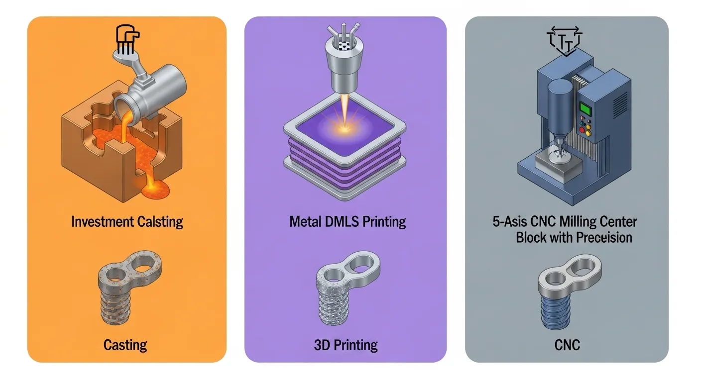
The client initially evaluated three processes: investment casting, metal 3D printing (DMLS), and CNC machining.
| Factor | Investment Casting | DMLS (Metal 3D Printing) | CNC Machining |
|---|---|---|---|
| Bore tolerance (±0.01mm) | Not achievable without post-machining | Needs post-machining | Direct |
| Surface finish Ra 0.4 µm | Not achievable | Ra 4–12 µm typical | Achievable |
| Lead time (14 days) | 4–6 weeks for tooling | 7–10 days but post-finish adds time | 14 days |
| Material (Ti-6Al-4V ELI) | Limited ELI grade availability | Supported | Full cert available |
| Regulatory traceability | Complex | Complex | Standard |
CNC machining was the only process that could hit the bore tolerance and surface finish directly, without secondary operations that would add risk to an already tight timeline. For medical parts where dimensional accuracy affects patient safety, this tradeoff matters more than unit cost.
For projects that combine complex geometry with strict tolerances, our 5-axis CNC milling delivers where casting and printing can't.
Precision CNC Machining for Medical Parts: FAQ
Q1: What tolerances can you hold for medical CNC machined parts?
We regularly hold ±0.01mm on bores and critical fits for implant-grade components. For less critical features, our standard is ±0.05mm. The right tolerance depends on the function and material — we'll review your drawing and confirm what's achievable before the quote.
Q2: What medical-grade materials do you machine?
We machine Titanium Grade 5 (Ti-6Al-4V ELI), Titanium Grade 23, 316L stainless steel, PEEK, and Aluminum 6061-T6. All materials come with mill certifications and full traceability documentation for medical device submissions.
Q3: Can you produce parts for clinical trials?
Yes. We support clinical trial batches with first-article inspection reports (FAIR), full dimensional data, material traceability, and documentation packages aligned with ISO 13485 requirements. We treat clinical batches with the same rigor as production.
Q4: How do you prevent titanium deformation during machining?
We use trochoidal toolpaths, high-pressure through-spindle coolant, custom fixturing for thin-wall sections, and conservative chip loads. For parts under 1mm wall thickness, we always run a first-piece confirmation before the full batch.
Q5: What's the minimum order quantity for precision medical CNC parts?
We can run single prototypes up to production volumes. For this type of medical housing, 10–25 parts is a common prototype batch. We scale to 500+ parts for pre-production validation runs.
Conclusion
Medical CNC machining isn't just about the machines. It's about the process discipline that sits around them — fixturing, toolpath strategy, in-process measurement, and thermal compensation.
This spinal implant housing project worked because we planned for failure before it happened. We tested fixturing on scrap material before touching clinical stock. We built compensation cycles into the boring operation. We ran the surface finish to Ra 0.31 µm instead of stopping at the 0.4 µm limit.
If you're working on a medical device that needs tight tolerances, biocompatible materials, or a full documentation package for regulatory submission, contact GD Prototyping for a free quote. We'll review your drawings, confirm feasibility, and give you a clear lead time within 24 hours.
