
A Complete Guide to the K‑Factor Sheet Metal Chart
Precision is the cornerstone of sheet metal fabrication. Every three-dimensional part, from a simple bracket to a complex enclosure, begins as a two-dimensional flat pattern. The ultimate accuracy of the final, bent part depends entirely on the accuracy of this initial flat pattern. A common question for designers is how to correctly calculate the dimensions of this flat pattern. The answer lies in understanding a single, critical variable that governs the physics of bending metal: the K-Factor.
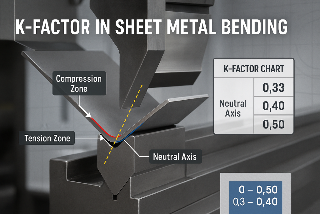
The K-Factor in sheet metal is a numerical ratio that defines the location of the neutral axis within the material during a bend. This value, typically between 0.33 and 0.50, is the essential variable for accurately calculating bend allowance. It is the key to creating a correct flat pattern that will fold perfectly into the desired 3D geometry.
As experts in precision sheet metal fabrication, GD-Prototyping relies on accurate bend calculations for every project. This guide provides a comprehensive, deep dive into the K-Factor. We will explain the science behind it, how it is used in the core bending formulas, and how to apply it in real-world scenarios.
The Physics of a Bend: Understanding the Neutral Axis
To understand the K-Factor, one must first understand what happens to a piece of metal when it is bent. The process is more complex than simply folding a piece of paper. Metal is a crystalline solid, and bending it forces these crystals to move and deform under immense pressure.
Compression and Tension in a Bend
When a flat sheet of metal is formed into a bend on a press brake, the material is subjected to two opposing forces.
- The material on the inside of the bend is compressed. The metal is forced to occupy a smaller space, causing it to increase in thickness slightly.
- The material on the outside of the bend is stretched. The metal is pulled apart, causing it to thin out slightly.
This simultaneous compression and tension is the fundamental dynamic of metal bending. The outer surface of the bend becomes longer than it was in the flat state, and the inner surface becomes shorter.
Defining the Neutral Axis
Somewhere between the compressed inner surface and the stretched outer surface, there is an imaginary plane that is neither compressed nor stretched. This plane is known as the neutral axis. The length of the neutral axis remains constant during the bending operation. Its length before the bend is the same as its arc length after the bend.
For this reason, the neutral axis is the single most important reference for all bend calculations. To create an accurate flat pattern, we must calculate the arc length of the neutral axis through the bend. This calculated length is what we add to the flat portions of the part to get the total pattern length.
Introducing the K-Factor
The K-Factor is the variable that tells us precisely where the neutral axis is located. It is a simple ratio. It represents the distance from the inside face of the material to the neutral axis (designated as "t") as a fraction of the total material thickness (designated as "T").
The formula is: K = t / T
A K-Factor of 0.50 means the neutral axis is located exactly in the center of the material's thickness. A K-Factor of 0.33 means the neutral axis is located closer to the inside face of the bend. In practice, the neutral axis is almost never in the exact center. Due to the complex stresses of bending, it always shifts slightly toward the inside surface. Therefore, the K-Factor is almost always less than 0.50.
The Core Formulas: Bend Allowance and Bend Deduction
The K-Factor is not a standalone number; its sole purpose is to be used within the core formulas that calculate the dimensions of a flat pattern. The two most important concepts in this calculation are Bend Allowance and Bend Deduction.
Bend Allowance (BA)
The Bend Allowance is the most direct application of the K-Factor. It is the arc length of the neutral axis as it goes through the bend. To calculate the total length of a flat pattern, a designer adds the Bend Allowance to the lengths of the flat sections (the flanges) of the part.
The formula for Bend Allowance is: BA = A * (π/180) * (IR + K * T)
Where:
- BA = Bend Allowance
- A = The bend angle in degrees (the angle the material is bent through).
- IR = The inside radius of the bend.
- K = The K-Factor.
- T = The material thickness.
This formula calculates the precise length of material needed to form the bend itself.
Bend Deduction (BD)
Bend Deduction is another common method used to calculate the flat pattern length. It approaches the problem from a different perspective. Instead of adding the Bend Allowance to the inside flange lengths, it involves subtracting a value (the Bend Deduction) from the total outside length of the part.
The calculation is slightly more complex. It first requires calculating the "Outside Setback" (OSSB), which is the distance from the vertex of the bend to the tangent point of the radius. The Bend Deduction is then calculated as two times the Outside Setback minus the Bend Allowance.
BD = (2 x OSSB) - BA
While both methods achieve the same result, Bend Allowance is generally considered the more direct and intuitive method for understanding the role of the K-Factor. Most modern CAD software uses the K-Factor and Bend Allowance as the primary calculation method.
The K-Factor Sheet Metal Chart
The value of the K-Factor is not a constant. It varies based on the material type, its condition (hardness), and the ratio of the bend radius to the material thickness. It is important to state that any K-Factor chart provides typical starting values for engineering estimates. The actual, precise K-Factor for a specific setup can only be determined through empirical testing with the exact material and tooling being used. However, this chart provides excellent baseline values for the design phase.
| Material Type | Condition | Bend Radius (R) / Thickness (T) Ratio | K-Factor Value |
| Aluminum | Soft (Annealed) | R/T < 1.0 | 0.35 |
| 1.0 < R/T < 3.0 | 0.40 | ||
| R/T > 3.0 | 0.50 | ||
| Aluminum | Hard (e.g., T6 Temper) | R/T < 1.0 | 0.40 |
| 1.0 < R/T < 3.0 | 0.45 | ||
| R/T > 3.0 | 0.50 | ||
| Mild Steel | Soft (Annealed) | R/T < 1.0 | 0.42 |
| 1.0 < R/T < 3.0 | 0.46 | ||
| R/T > 3.0 | 0.50 | ||
| Stainless Steel | Soft (Annealed) | R/T < 1.0 | 0.40 |
| 1.0 < R/T < 3.0 | 0.45 | ||
| R/T > 3.0 | 0.50 | ||
| Stainless Steel | Hard (e.g., Full Hard) | R/T < 1.0 | 0.44 |
| 1.0 < R/T < 3.0 | 0.48 | ||
| R/T > 3.0 | 0.50 |
Practical Application: Worked-Out Examples
The best way to understand the K-Factor and Bend Allowance is to walk through a real-world calculation.
How to Use the K-Factor in a Real-World Scenario
Let's use the formulas and the chart to determine the correct flat pattern length for a simple L-shaped bracket.
Example 1: A 90-Degree Bend in Mild Steel
- Material: 2.0 mm thick Mild Steel (Soft)
- Inside Bend Radius (IR): 2.0 mm
- Bend Angle (A): 90 degrees
- Flange 1 Length: 50 mm
- Flange 2 Length: 30 mm
Step 1: Find the K-Factor from the chart. First, we calculate the R/T ratio.
- R/T = 2.0 mm / 2.0 mm = 1.0
- Looking at the chart for "Mild Steel (Soft)" where R/T = 1.0, we find the K-Factor is 0.46.
Step 2: Calculate the Bend Allowance (BA). Now, we plug our values into the Bend Allowance formula.
- BA = A * (π/180) * (IR + K * T)
- BA = 90 * (3.14159 / 180) * (2.0 + 0.46 * 2.0)
- BA = 1.5708 * (2.0 + 0.92)
- BA = 1.5708 * 2.92
- BA = 4.587 mm
Step 3: Calculate the Total Flat Pattern Length. The total length is the sum of the flat sections plus the Bend Allowance. The flat sections are calculated from the tangent points of the bend, which is the total flange length minus the bend radius and the thickness.
- Flat Length 1 = 50 mm - (IR + T) = 50 - (2.0 + 2.0) = 46 mm
- Flat Length 2 = 30 mm - (IR + T) = 30 - (2.0 + 2.0) = 26 mm
- Total Length = Flat Length 1 + Flat Length 2 + BA
- Total Length = 46 mm + 26 mm + 4.587 mm
- Total Flat Pattern Length = 76.587 mm
Example 2: A 60-Degree Bend in Hard Aluminum
- Material: 3.0 mm thick Hard Aluminum
- Inside Bend Radius (IR): 6.0 mm
- Bend Angle (A): 60 degrees
- Flange 1 Length: 40 mm
- Flange 2 Length: 40 mm
Find the K-Factor.
- R/T = 6.0 mm / 3.0 mm = 2.0
- For "Hard Aluminum" where R/T is between 1.0 and 3.0, the K-Factor is 0.45.
Calculate the Bend Allowance (BA).
- BA = 60 * (π/180) * (6.0 + 0.45 * 3.0)
- BA = 1.0472 * (6.0 + 1.35)
- BA = 1.0472 * 7.35
- BA = 7.697 mm
Calculate the Total Flat Pattern Length.
- Flat Length 1 = 40 mm - (IR + T) = 40 - (6.0 + 3.0) = 31 mm
- Flat Length 2 = 40 mm - (IR + T) = 40 - (6.0 + 3.0) = 31 mm
- Total Length = 31 mm + 31 mm + 7.697 mm
- Total Flat Pattern Length = 69.697 mm
Factors That Influence the K-Factor in Practice
The values in the chart are excellent starting points. However, in a real-world fabrication environment, several factors can cause the actual K-Factor to deviate slightly. An expert sheet metal fabricator understands these variables and can adjust for them to achieve the highest precision.
Why Might Your K-Factor Be Different?
- Material Properties: The exact hardness, ductility, and grain direction of a specific batch of metal can vary slightly from the published standard. A harder material will have a different neutral axis location than a softer one.
- Bending Method: The way the metal is bent has a significant impact. The most common method is "air bending" on a press brake, where the punch pushes the metal into a V-die without it touching the bottom. A different method, "bottoming," involves coining the material at the bottom of the stroke, which changes the internal stresses and shifts the K-Factor.
- Tooling: The specific tooling used on the press brake is a major factor. The sharpness of the punch radius and the width of the V-die opening both influence how the material deforms and where the neutral axis settles.
- Bend Direction: The direction of the bend relative to the grain of the sheet metal can also cause minor variations in the K-Factor.
All of these real-world variables are considered by expert fabricators and are a key part of our comprehensive Sheet Metal Design Guidelines.
The Role of K-Factor in Modern CAD Software
Modern 3D CAD software (like SolidWorks, Inventor, or Fusion 360) has powerful built-in sheet metal features. These tools automate the process of creating a flat pattern. However, the software is not magic. It relies on the user to input the correct parameters.
When a designer creates a sheet metal part in CAD, they must define the material thickness, the inside bend radius, and a bend allowance factor. This factor is most often the K-Factor. The software then uses the exact formulas described in this guide to automatically calculate the correct flat pattern. The accuracy of the software's output is therefore completely dependent on the accuracy of the K-Factor value that is entered. Using a generic default value can lead to inaccurate flat patterns and parts that do not meet their final dimensional specifications. The final quality of the part is also impacted by the choice of Sheet Metal Finishing Options.
Conclusion
The K-Factor is a fundamental concept in precision sheet metal fabrication. It is the crucial link that connects the three-dimensional designed part to the two-dimensional flat pattern required for manufacturing. While it is a simple ratio, it represents the complex physics of how metal deforms under pressure. A correct K-Factor leads to an accurate bend allowance, a precise flat pattern, and a final part that meets every specification.
Understanding the principles behind the K-Factor empowers engineers to create more intelligent and manufacturable designs. At GD-Prototyping, our fabrication process is built on a foundation of these precise calculations. We combine deep engineering knowledge with hands-on expertise to transform your complex designs into perfectly formed physical components.