
ABS Wall Thickness for Injection Molding: A Complete Guide
Acrylonitrile Butadiene Styrene (ABS) is a true workhorse in the world of injection molding. This versatile thermoplastic is prized for its excellent balance of properties. It offers high impact strength, good rigidity, and a high-quality surface finish. This makes it a top choice for countless applications, from electronic housings to automotive interiors. However, the success of any part molded from ABS is highly dependent on one key design rule: proper wall thickness.
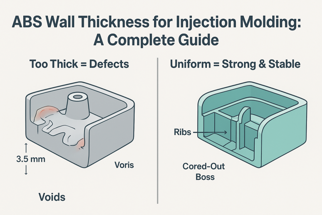
The recommended wall thickness for ABS in injection molding is typically between 1.5 mm and 3.5 mm (0.060 to 0.140 inches). More importantly, maintaining a uniform, consistent thickness within this range is the single most critical factor for preventing cosmetic defects, minimizing internal stress, and ensuring the part's dimensional stability.
This guide provides a deep, technical dive into the principles of ABS wall thickness. As an expert in Design for Manufacturability (DFM) for ABS components, GD-Prototyping will explain the science behind the rules. We will detail the consequences of incorrect thickness. We will also provide actionable best practices for designing successful, high-quality ABS parts.
Why Wall Thickness is the Most Critical Design Rule for ABS
To understand why wall thickness is so critical, we must first look at the physics of the injection molding process and the specific properties of ABS plastic. An injection molded part is not simply formed; it is born from a process of intense heat and pressure, followed by a crucial cooling phase.
The Physics of Molten ABS
When ABS pellets are heated in an injection molding machine, they become a viscous, molten liquid. This liquid is then injected at high pressure into a cooled mold cavity. The molten plastic flows through the cavity, filling every detail of the part's geometry. Once the cavity is full, the plastic begins to cool and solidify, starting from the outside surfaces that are in contact with the cooler mold walls.
A key property of ABS, like all thermoplastics, is that it shrinks as it cools. This shrinkage is not insignificant; it can be up to 0.7% of the material's volume. The entire science of plastic part design is built around managing this shrinkage in a controlled and predictable way.
The Importance of Uniform Cooling
The core principle is uniform cooling. If every section of a part cools and shrinks at the same rate, the part will be stable and free of defects. However, if one section of a part is significantly thicker than another, it will cool much more slowly.
Consider a part with a 2 mm wall adjacent to a thick, 6 mm boss.
- The 2 mm wall will cool and solidify relatively quickly.
- The 6 mm boss, being much thicker, will remain molten in its core for a much longer time.
As this thick core finally cools and shrinks, it will pull on the surrounding, already-solid material. This differential shrinkage creates immense internal stress within the part. This stress is the root cause of nearly all major molding defects.
The Link Between Thickness and Cycle Time
Beyond part quality, wall thickness has a direct and dramatic impact on the cost of production. The cooling phase is often the longest part of the entire injection molding cycle. The time it takes for a part to cool sufficiently to be ejected is exponentially related to its thickest section. A part that is twice as thick can take four times as long to cool. In a mass production environment, every second of cycle time adds to the final cost per part. Designing with the minimum appropriate wall thickness is therefore essential for creating an economical product.
The Consequences of Incorrect Wall Thickness
When the fundamental rule of uniform wall thickness is violated, the internal stresses caused by differential cooling will manifest as a variety of molding defects. These can range from minor cosmetic blemishes to severe structural flaws that render the part unusable.
What Happens When Walls Are Too Thick or Non-Uniform?
Understanding these common defects is crucial for any designer working with ABS.
Sink Marks: The Most Common Defect
- What They Are: Sink marks are shallow depressions or dimples on the surface of a molded part. They typically appear on the face opposite a thick feature like a rib, boss, or a sharp corner.
- Why They Happen: Sink marks are a direct result of differential shrinkage. As the thick, molten core of a feature (like a rib) cools and shrinks, it pulls the still-soft surface of the main wall inward. This creates the characteristic indentation. The thicker the feature, the more it will shrink, and the more severe the sink mark will be.
- Impact: Sink marks are primarily a cosmetic defect. However, on high-visibility consumer products, they are often unacceptable and can lead to part rejection. Preventing these flaws is a primary goal of good part design. For more information, our detailed guide provides a range of Sink Marks Fixes.
Voids: The Hidden Internal Flaw
- What They Are: Voids are air bubbles or vacuum pockets that are trapped inside a thick section of a molded part.
- Why They Happen: Voids are an extreme consequence of the same mechanism that causes sink marks. In a very thick section, the outer surfaces of the plastic freeze and solidify first. As the large, molten core continues to cool and shrink, it pulls away from itself, but the rigid outer skin cannot collapse inward to form a sink mark. Instead, a vacuum bubble, or void, is formed in the center.
- Impact: Voids are a serious structural defect. They create a weak point within the part that can lead to unexpected mechanical failure under load. Because they are internal, they are often invisible without cutting the part open or using advanced inspection methods like X-ray.
Warping: The Distortion of Form
- What It Is: Warping is the dimensional distortion of a part after it has been molded. A part that was designed to be flat may come out of the mold twisted or bowed.
- Why It Happens: Warping is the result of large-scale, uncontrolled internal stresses. When a part has significant variations in wall thickness, different sections cool and shrink at drastically different rates. This creates a massive internal tug-of-war. After the part is ejected from the mold, these stresses relieve themselves by bending and twisting the part into a new, lower-energy shape.
- Impact: A warped part will not fit correctly in an assembly. It is a functional failure and a clear sign of a poor part design.
Short Shots: When Walls Are Too Thin
- What They Are: A short shot is an incomplete part. The molten plastic fails to fill the entire mold cavity before it freezes.
- Why They Happen: This defect occurs when a wall section is too thin for the molten plastic to flow through. The thin channel causes the plastic to cool and solidify prematurely, creating a blockage that prevents the rest of the cavity from filling. The flowability of the plastic (its melt flow index) and the injection pressure are also factors.
- Impact: A short shot is a total failure. The part is incomplete and must be scrapped.
Best Practices for Achieving Uniform Wall Thickness
The goal of a designer is to create a part that is strong and functional while maintaining a perfectly uniform wall thickness. This is often a challenging task. However, a set of established best practices can guide the design process.
How Can Designers Maintain Uniformity?
Instead of adding material, the key is often to remove it strategically.
The "Coring Out" Technique
The most fundamental best practice is to "core out" solid sections. Imagine you need to design a thick, solid block. Instead of molding it as a solid piece, which would result in extreme sink and voids, you should design it as a hollowed-out box. By removing the internal material, you create a part with a consistent, uniform wall thickness. This eliminates the root cause of differential shrinkage. Any solid-looking feature on a plastic part should be cored out from the back or bottom.
Designing Ribs for Stiffness, Not Thickness
If a wall needs to be stronger or stiffer, the first instinct is often to make it thicker. This is almost always the wrong approach. A much better solution is to maintain a thin nominal wall and add a series of thin support ribs. Ribs can dramatically increase the stiffness of a part with a minimal increase in material. To prevent them from causing sink marks on the opposite face, ribs must be designed correctly.
- Rib Thickness: A rib should be approximately 40% to 60% of the thickness of the wall it is attached to. For example, a 2.5 mm wall should have ribs that are 1.0 mm to 1.5 mm thick.
- Rib Height: The height of a rib should generally not exceed three times the nominal wall thickness.
- Rib Spacing: Ribs should be spaced at least two times the nominal wall thickness apart from each other.
Designing Bosses for Mounting Points
Bosses are cylindrical features used for screws and mounting points. A solid, thick boss is a major cause of sink marks and voids.
- Boss Wall Thickness: The walls of a boss should also follow the 40-60% rule relative to the main wall.
- Coring: The boss must be cored out.
- Gussets: Instead of adding a thick base to a boss for support, it is better to add thin support gussets or ribs that connect it to the main wall.
Managing Transitions in Thickness
In some cases, a change in wall thickness is unavoidable. When this is necessary, the transition must be gradual, not a sharp, sudden step. A sharp step creates a point of high stress concentration and will cause defects. The best practice is to use a gentle, ramped, or chamfered transition. A good rule of thumb is that the transition length should be at least three times the change in thickness.
The ABS Wall Thickness Rule-of-Thumb Table
This table provides a quick reference for the key design rules and best practices discussed in this guide. Using this as a checklist during the design process can help prevent the most common molding defects.
| Feature | Recommended Dimension / Rule | Reason / Best Practice |
| Nominal Wall Thickness | 1.5 mm - 3.5 mm (0.060" - 0.140") | Balances strength with manufacturability. Ensures proper melt flow and reasonable cooling times. |
| Rib Thickness | 40% - 60% of Nominal Wall | Prevents sink marks on the opposite cosmetic surface while providing stiffness. |
| Boss Wall Thickness | 40% - 60% of Nominal Wall | Prevents sink marks and voids at the base of the boss. |
| Radius on Inside Corners | Minimum of 0.5 × Nominal Wall | Reduces stress concentration and improves molten plastic flow. |
| Draft Angle | 1 - 2 degrees per side (minimum) | Allows the part to be ejected from the mold without drag marks or damage. |
A proper Draft Angle for Injection Molding is a critical, related principle. It is just as important as wall thickness for creating a successful and manufacturable part.
Beyond the Rules: Exceptions and Consideration
While the rule of uniform wall thickness is paramount, there are a few exceptions and advanced considerations.
Are There Exceptions to the Uniform Wall Thickness Rule?
Certain special features, like living hinges, require a very thin section of material to allow for flexibility. These are designed with a deep understanding of material properties and molding principles and are a clear exception to the general rule.
Additionally, some special grades of ABS are filled with materials like glass fiber. These fillers can significantly reduce the material's overall shrinkage rate. This may allow for the successful molding of slightly thicker sections than would be possible with an unfilled grade of ABS.
For any part that must intentionally deviate from the standard rules, an advanced simulation technique called Mold Flow Analysis (MFA) is strongly recommended. MFA software simulates the flow of molten plastic into the mold cavity. It can predict potential problems like short shots, air traps, and areas of high stress. This allows designers to correct these issues digitally before any steel is cut for the expensive mold.
Conclusion
Mastering the principles of wall thickness is the key to designing successful injection molded parts with ABS. The fundamental goal is to achieve uniform cooling across the entire part. This is accomplished by maintaining a consistent wall thickness within the recommended range of 1.5 mm to 3.5 mm. By using design techniques like coring out thick sections and adding thin, well-proportioned ribs and bosses, engineers can create parts that are strong, lightweight, and free from cosmetic and structural defects.
Adhering to these best practices is the most effective way to ensure a part is manufacturable, functional, and economical. At GD-Prototyping, our team of engineers provides expert Design for Manufacturability (DFM) feedback on every project. We help our clients optimize their designs to prevent molding issues and achieve the highest quality results.