
Injection Molding Gate Types: A Complete Guide on How to Choose
In the complex world of injection molding, a successful part is the result of hundreds of precise, interconnected decisions. Among the most critical of these is the design of the gate. The gate is often one of the smallest and simplest-looking features of a mold. However, its design and location have an outsized impact on the final part's cosmetic quality, structural integrity, and the overall efficiency and cost of the manufacturing process. Choosing the right gate is a foundational step in Design for Manufacturability (DFM).
An injection molding gate is a small, precise opening in the mold tool that allows molten plastic to flow from the runner system into the part cavity. After the part is filled, the gate must freeze off, separating the part from the runner. The type of gate chosen affects everything from material flow and internal stresses to the final appearance of the product.
As experts in advanced mold design and manufacturing, GD-Prototyping understands that proper gate selection is a science. This guide provides a deep, technical dive into the most common gate types. We will explain how they work, their specific pros and cons, and the critical factors to consider when choosing the right gate for your application.
The Critical Functions of an Injection Molding Gate
To appreciate the importance of gate design, it is essential to understand the many roles this small feature plays during the molding cycle. It is not merely a doorway for plastic; it is a highly engineered control valve.
Controlling the Flow of Plastic
The size and shape of the gate control the speed and pressure at which the molten plastic enters the cavity. A small gate increases the shear rate of the plastic, which can affect its final properties. A large gate allows for a faster, less stressful fill. The gate design is a primary tool for the process engineer to control the filling pattern and ensure the cavity is packed out completely and uniformly.
Freezing Off the Part
After the cavity is filled, the machine enters the "holding" or "packing" phase. During this phase, it continues to apply pressure to force more material into the cavity, compensating for the shrinkage that occurs as the plastic cools. The gate is designed to be the thinnest point in the flow path. This allows it to cool and solidify (or "freeze off") first. Once the gate freezes, it effectively seals the part off from the runner system. This allows the part to be held under pressure while the rest of the runner system begins to cool.
Managing Aesthetics
Every gate leaves a mark, or vestige, on the part where it was attached. This small blemish can be a critical cosmetic concern. A major part of the design process is deciding where to locate the gate so that this vestige is on a non-visible or non-critical surface of the final product. The type of gate chosen also determines the size and appearance of this vestige.
Influencing Overall Part Quality
The location of the gate has a profound impact on the final quality of the molded part. It determines the direction of material flow, which in turn influences the location of weld lines, the degree of warpage, and the potential for cosmetic defects. An improperly placed gate can be the root cause of many common molding problems.
Manually Trimmed Gates: Simplicity and Flow
The first major category of gates is those that require a manual secondary operation to remove the runner system from the part. These gates are generally simpler and less expensive to machine into the mold, making them a common choice for many applications.
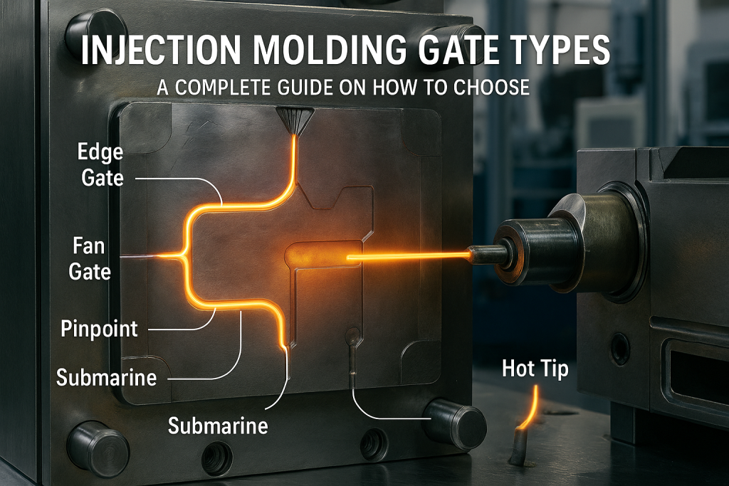
The Edge Gate (or Standard Gate)
The edge gate is the most common and simplest type of gate. It consists of a rectangular channel machined into the parting line of the mold, allowing plastic to enter at the side of the part.
How it Works: The gate connects the runner directly to the edge of the part cavity. After ejection, the part and the runner are removed as a single piece. An operator must then manually trim or break the gate to separate the part.
Pros: Simple to design and manufacture, making it low-cost. Its large cross-section allows for good material flow and packing pressure, which is good for larger parts.
Cons: Requires a manual de-gating operation, which adds labor cost and cycle time. The gate vestige is on the edge of the part and can be quite noticeable.
Best Applications: Flat, rectangular parts where the edge of the part is not a critical cosmetic surface. It is very common in consumer products and industrial housings.
The Fan Gate
A fan gate is a variation of the edge gate. It starts small at the runner and widens into a "fan" shape as it meets the part cavity.
How it Works: The wide gate front spreads the flow of plastic over a larger area. This reduces the stress on the material as it enters the cavity. Like an edge gate, it requires manual trimming after molding.
Pros: Ideal for large, flat parts that are prone to warping. The wide flow front reduces internal stress and improves dimensional stability. It is also good for fragile parts where a concentrated flow could cause damage.
Cons: It leaves a very long gate vestige that requires careful manual trimming. It can be more difficult to control the flow pattern precisely.
Best Applications: Large, flat components like electronic enclosure panels, trays, or covers where minimizing warpage is the primary concern.
The Tab Gate
The tab gate is another variation of the edge gate, designed to reduce shear stress on the part itself.
How it Works: The gate flows into a small, auxiliary tab that is adjacent to the main part cavity. The part is then filled from this tab. This means the high-stress injection flow is absorbed by the tab, not the final part.
Pros: Excellent for molding thin, flat parts with shear-sensitive materials like polycarbonate (PC). It improves the optical and mechanical properties of the part by creating a uniform, low-stress flow front.
Cons: The tab must be manually trimmed off, which is an additional operation. It also creates slightly more material waste.
Best Applications: Optically clear parts like lenses or light pipes, and thin-walled components where preventing material degradation from high shear is critical.
Automatically Trimmed Gates: Efficiency and Automation
The second major category of gates is those that are designed to shear off from the part automatically during the mold opening or ejection sequence. These gates eliminate the need for a manual trimming operation, which reduces labor costs and cycle times, making them ideal for high-volume production.
The Pinpoint Gate (or Pin Gate)
A pinpoint gate is a very small, round gate, typically located on the parting line of a three-plate mold.
How it Works: In a three-plate mold, the runner system is on a separate plate. As the mold opens, the runner is pulled away first, which shears the small, delicate pin gate cleanly from the part's surface.
Pros: The gate is sheared automatically. It leaves a very small, almost invisible vestige (the "pinpoint"). It can be located almost anywhere on the part's surface.
Cons: The small size of the gate can create high shear stress. It is not suitable for some shear-sensitive or highly filled materials. Requires a more complex and expensive three-plate mold.
Best Applications: High-volume production of cosmetic parts where a minimal gate vestige is required. Common in consumer goods and small electronic components.
The Submarine Gate (or Tunnel Gate)
A submarine gate is one of the most popular and versatile automated gate types. It is machined into the core or cavity half of the mold, below the parting line.
How it Works: The gate follows an angled, cone-shaped tunnel. It injects plastic into the side of the part, often near an ejector pin. As the part is ejected from the mold, the runner is held in place, and the forward motion of the part shears the gate off at the tunnel's sharp edge.
Pros: The gate is automatically trimmed. The gate vestige is located on a non-cosmetic side or bottom surface of the part, effectively hiding it from view.
Cons: It is more complex to machine into the mold than a simple edge gate. The small gate can cause high shear stress. It can be difficult to remove if it breaks off inside the tunnel.
Best Applications: High-volume production of parts where the cosmetic appearance of the main surfaces is critical. This is a very common choice for aesthetically demanding consumer products.
The Hot Tip Gate (Part of a Hot Runner System)
A hot tip gate is not just a feature of the mold steel; it is part of an integrated, heated runner system.
How it Works: In a hot runner system, the entire runner is kept molten inside a heated manifold. A heated nozzle extends from this manifold and delivers the molten plastic directly to the part surface, forming a tiny gate. The gate freezes off between shots, but the material in the nozzle remains liquid, ready for the next cycle.
Pros: There is no runner waste, which saves significant material costs. It provides exceptional process control. It leaves a very small, clean gate vestige.
Cons: Hot runner systems are extremely complex and expensive. They represent a major increase in the initial tool cost. They are also more difficult to maintain.
Best Applications: Mass production of consumer goods like bottle caps, medical parts like syringe barrels, and automotive components. The high cost of hot runner systems is a key consideration when choosing between Rapid Tooling vs Production Tooling.
A Comparison of Common Gate Types
| Gate Type | Trimming Method | Vestige Size | Relative Tool Cost | Ideal Application |
| Edge Gate | Manual | Medium to Large | Low | General purpose, flat parts. |
| Fan Gate | Manual | Large | Low | Large, flat parts prone to warping. |
| Submarine Gate | Automatic | Small (Hidden) | Moderate | High-volume cosmetic parts. |
| Hot Tip Gate | Automatic (None) | Very Small | Very High | Mass production, no material waste. |
How to Choose the Right Gate for Your Part
The selection of the right gate is a technical decision that balances four key factors. An expert mold designer will analyze these factors to propose the optimal solution for a given project.
A Systematic Approach to Gate Selection
Consider the Plastic Material: The material's properties are a primary consideration. Highly viscous materials may require a larger gate to fill properly. Shear-sensitive materials like polycarbonate may require a tab gate to prevent material degradation. The molding temperature of the material will also influence the gate design, as it must freeze off at the correct point in the cycle.
Analyze the Part Geometry: The size and shape of the part heavily influence the choice. A large, flat part is a good candidate for a fan gate to minimize warpage. A small, complex part may require multiple pinpoint gates to fill evenly. A part with very thin walls may need a gate that allows for a very fast injection speed to prevent a short shot.
Define the Cosmetic Requirements: This is often the most important factor from the client's perspective. Where can the gate vestige be located? If the part is a highly visible cosmetic housing, the gate must be located on an internal, non-visible surface. This would immediately point to a submarine gate or a hot tip gate. If the part is an internal structural component, a simple and robust edge gate may be perfectly acceptable.
Evaluate the Production Volume: The expected production quantity is a critical financial driver. For a low-volume run of a few thousand parts, the added cost of a complex automated gate or a hot runner system is not justifiable. A simple, manual edge gate is the most economical choice. For a mass-produced part that will be made in the millions, the material savings from a hot runner system and the labor savings from automated de-gating will easily pay back the high initial tool cost.
How Gate Design Impacts Part Quality
The gate is not just a doorway; it is the control point for many common molding defects. Intelligent gate design is a powerful tool for improving overall part quality.
Preventing Sink Marks
A properly sized and located gate is essential for applying sufficient holding pressure to the part. This holding pressure forces additional material into the cavity as the part cools, which compensates for shrinkage. A gate that is too small will freeze off too early, cutting off this vital pressure and leading to defects. This is a primary tool in our guide to Sink Marks Fixes.
Managing Weld Lines
A weld line is formed when two or more fronts of molten plastic meet inside the mold cavity. These lines can be both cosmetic and structural weak points. The location of the gate or gates directly determines the flow pattern of the plastic and, therefore, the final location of any weld lines. A mold designer can strategically place the gate to move weld lines to less critical or non-visible areas of the part.
Reducing Warpage
Warpage is caused by non-uniform shrinkage and internal stress. The gate design can help to manage this. For example, on a long part, using two gates instead of one can create a more balanced filling pattern. A fan gate spreads the filling pressure over a wide area. Both of these techniques can help to reduce the internal stresses that lead to warpage. For very low volumes where tooling cost is a barrier, it is also worth exploring other processes. A comparison of Vacuum Casting vs Injection Molding can reveal alternative paths.
Conclusion
The injection molding gate is a small feature with a massive impact. It is a critical element of mold design that influences every aspect of the final part, from its cosmetic appearance and structural strength to the speed and cost of its production. The choice between a simple manual gate and a complex automated one is a strategic decision. It requires a careful analysis of the part's material, geometry, quality requirements, and production volume.
Partnering with an experienced mold design and manufacturing expert is the key to ensuring the right choice is made. At GD-Prototyping, our team of engineers has deep expertise in designing molds with the optimal gate type for every unique application. We leverage this knowledge to help our clients produce the highest quality parts in the most efficient way possible.