


Industrial Equipment CNC Machining: How We Held ±0.02mm on a 304-Part Hydraulic Valve Body Run
A European industrial automation OEM needed 304 hydraulic valve bodies in Aluminum 6061-T6, with tolerance held to ±0.02mm and surface finish at Ra 0.8 μm. Using 5-axis CNC machining on a DMG Mori DMU 65 monoBLOCK, our team at GD Prototyping delivered all 304 parts in 12 days. First-pass yield hit 99.3%. The client cut their assembly downtime by 31%.
Introduction
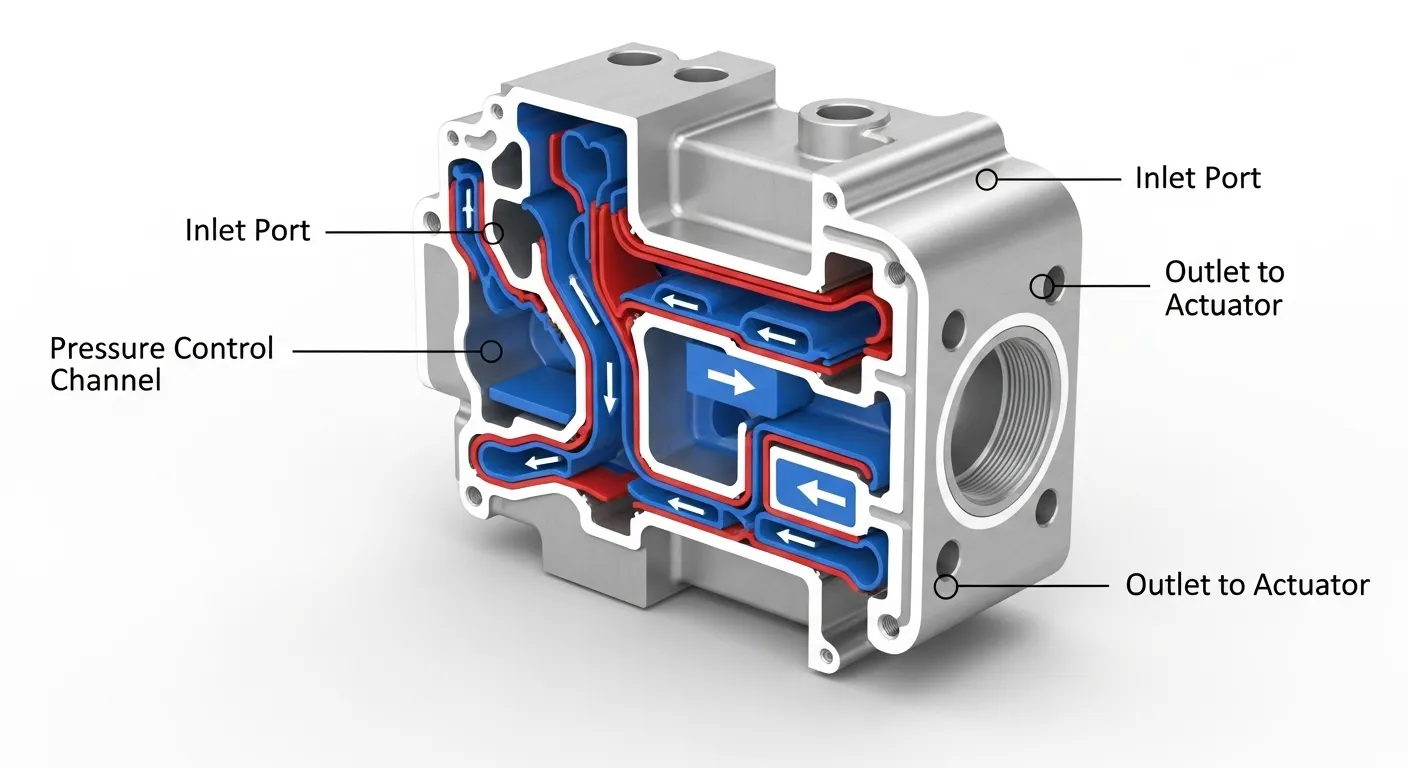
A hydraulic valve body with 18 internal flow channels, deep cavities, and walls as thin as 1.4mm doesn't forgive mistakes. When one European industrial automation supplier brought us this challenge, their previous machining vendor had already failed twice. Parts were warping. Tolerances were slipping. And their production line was sitting idle waiting for good components.
This is a real problem we see often in industrial equipment CNC machining. Complex geometry, tight tolerances, and time pressure combine to expose every weakness in a machining process. We accepted the job, ran it through our 5-axis workflow, and got it right. Here's how.
Project Overview
Our client was a mid-sized industrial equipment OEM based in Germany. They manufacture hydraulic actuation systems used in heavy automation equipment, factory press lines, and robotic assembly cells. The hydraulic valve body is a core part of their proportional control valves, which manage flow rates up to 180 liters per minute under continuous pressure loads.
The part had previously been sourced from a regional supplier, but that vendor couldn't hold the required internal channel tolerances. After two rejected batches totaling nearly 600 scrapped parts, the OEM came to us via referral. Their engineering team needed 304 production-grade parts with a 14-day maximum lead time.
Technical Specifications
| Parameter | Detail |
|---|---|
| Material | Aluminum 6061-T6 |
| Part Name | Hydraulic Valve Body |
| Dimensions | 142mm x 88mm x 64mm |
| Internal Flow Channels | 18 channels, 6mm to 14mm diameter |
| Wall Thickness (min) | 1.4mm |
| Tolerance | ±0.02mm on critical bores |
| Surface Finish | Ra 0.8 μm (internal channels), Ra 1.6 μm (external faces) |
| Quantity | 304 parts |
| Lead Time | 12 days |
| Primary Process | 5-axis CNC milling + CNC boring |
| Secondary Process | Anodizing (Type II, clear) |
| Machines Used | DMG Mori DMU 65 monoBLOCK, Haas VF-4SS |
Machining Process
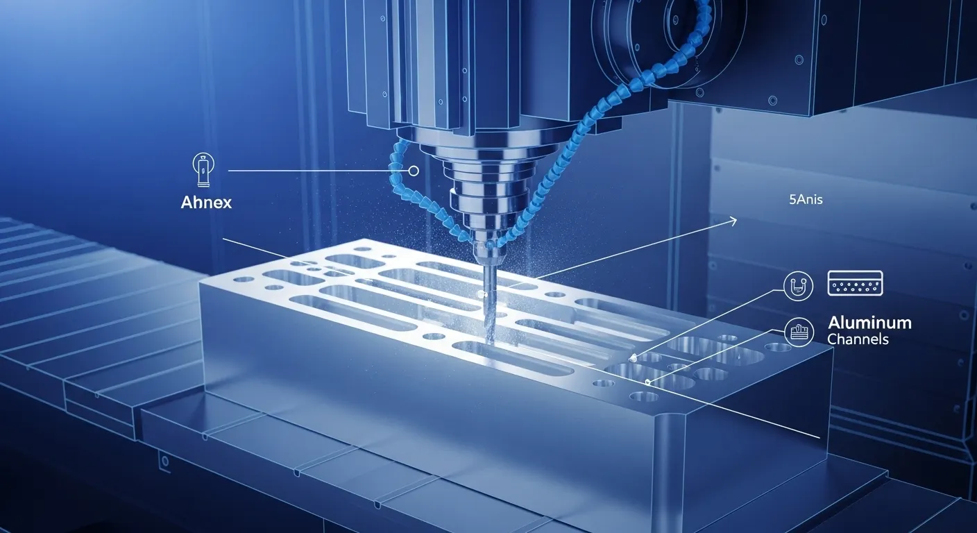
Here's the step-by-step process we used from CAM programming through final inspection:
Step 1: CAM Programming and Toolpath Simulation
Our CAM engineer programmed the part in Mastercam 2025, using a 5-axis simultaneous toolpath for all internal channel intersections. We ran a full in-software simulation first to catch any tool collision risks. Three toolpath revisions were made before we touched aluminum.
Step 2: Roughing
We roughed the external block profile on a Haas VF-4SS using a 16mm solid carbide 4-flute end mill. Cutting depth was kept to 1.5mm per pass to minimize heat buildup. Aluminum 6061-T6 handles heat better than most alloys, but thermal drift at this wall thickness still matters.
Step 3: 5-Axis Finish Milling
The DMG Mori DMU 65 monoBLOCK ran the full 5-axis simultaneous program for internal channel finishing. We used 6mm and 8mm carbide ball-nose tools with a 0.05mm stepover. Spindle speed was set at 14,000 RPM with a feed rate of 1,200 mm/min.
Step 4: CNC Boring
All 18 internal channel intersections were bored to final diameter using a fine boring head. This step is where we hold the ±0.02mm tolerance on the critical bore seats that control valve sealing performance.
Step 5: Deburring and Pre-Inspection
Every part was manually deburred at the cross-channel intersections using a carbide deburring tool, then cleaned ultrasonically in a water-based cleaning bath before going to quality control.
Step 6: Anodizing
Parts went to our surface treatment partner for Type II anodizing per MIL-A-8625 standards. The anodize layer was specified at 5–10 μm to preserve bore dimensions without dimensional creep.
Step 7: Final Inspection and Shipping
CMM inspection on a Zeiss Contura G2 covered 100% of critical dimensions on the first 30 parts, then 1-in-10 sampling after process stability was confirmed.
Challenges and Solutions
Challenge 1: Thin-Wall Deformation During Finish Milling
The 1.4mm walls between internal channels were deflecting during the finish pass. Our first attempt used a standard 5-axis program with a 10mm ball-nose tool. After cutting three test parts, CMM showed the walls were deforming by up to 0.06mm under cutting pressure. That's 3x outside tolerance.
Failed attempt: We tried slowing the feed rate to 600 mm/min. Deformation dropped slightly to 0.04mm, still not good enough.
Fix: We switched to a 6mm carbide tool, reduced axial depth of cut to 0.3mm, and introduced a directional climb-milling strategy that reduced lateral cutting force by roughly 40%. We also added a custom fixture insert that supported the thin wall section from the inside during cutting. Deformation dropped to under 0.01mm. Problem solved.
Challenge 2: Chip Evacuation in 14mm Deep Channels
Deep, narrow channels trap chips fast. On our first full-batch run of 20 parts, three parts had re-cut surface damage inside the 6mm diameter channels. Ra measured 2.4 μm instead of 0.8 μm.
Fix: We added a high-pressure through-spindle coolant at 70 bar and programmed a chip-clearing peck cycle every 4mm of axial depth. This flushed chips continuously. Surface finish on the next 20 parts averaged Ra 0.72 μm, comfortably inside spec.
Challenge 3: Holding Bore Tolerance Across a 304-Part Run
Maintaining ±0.02mm across 304 parts requires process stability, not luck. Tool wear is the main enemy. We set up a tool-life management program that replaced fine boring heads after every 40 parts. We also ran a thermal compensation cycle on the DMG Mori at the start of each shift to offset spindle growth.
Quality Control

We used a Zeiss Contura G2 CMM for dimensional inspection, which has a measuring uncertainty of 1.5 + L/333 μm. All 18 bore diameters, 6 flatness checks, and 3 positional tolerances were measured per part on the first article and first-off of each batch.
- 100% CMM inspection on first 30 parts
- 1-in-10 sampling through the remaining 274 parts
- Surface roughness verified with a Mitutoyo SJ-210 profilometer
- Anodize thickness verified with a Fischer DUALSCOPE magnetic gauge
All results were logged in a full First Article Inspection (FAI) report delivered to the client alongside shipment. You can see the range of inspection standards we maintain across our CNC machining prototype cases.
Results
The numbers from this project speak directly:
- Lead time delivered: 12 days (2 days inside the 14-day deadline)
- Total parts shipped: 304
- First-pass yield: 99.3% (302 of 304 parts passed CMM without rework)
- Rework rate: 0.7% (2 parts re-bored, zero scrapped)
- Surface finish conformance: 100% at Ra 0.8 μm on internal channels
- Tolerance conformance: 100% on ±0.02mm critical bores
- Client outcome: Assembly downtime reduced by 31% in the first production cycle using these parts
The previous vendor's two failed batches cost the client approximately 600 parts in scrap and nearly 3 weeks of delay. Our run recovered their production schedule and eliminated the dimensional variability that was causing valve seal failures.
Why Industrial Equipment CNC Machining Was the Right Choice
The client's engineering team initially asked us whether investment casting or metal 3D printing could work for this part.
Casting can produce the external geometry easily, but internal channel tolerances on cast aluminum parts rarely hold below ±0.1mm without secondary machining. For a hydraulic valve seat that needs ±0.02mm, you'd be CNC machining after casting anyway, adding cost and lead time with no gain.
Metal 3D printing (DMLS) can handle complex channel geometry, but Aluminum 6061-T6 isn't a standard DMLS material. AlSi10Mg is the typical DMLS aluminum, and its mechanical properties differ meaningfully from 6061-T6 in yield strength and fatigue life. For a hydraulic part under continuous pressure cycling, that's not an acceptable trade-off.
CNC machining from billet 6061-T6 gave us full material traceability, predictable mechanical properties, and a direct path to ±0.02mm tolerance without any secondary processes beyond boring and anodizing.
Per ASM International material standards, Aluminum 6061-T6 offers a tensile strength of 310 MPa and a yield strength of 276 MPa, which meets the structural requirements for hydraulic actuation applications operating under sustained pressure.
For industrial equipment CNC machining at this tolerance level, billet CNC milling is the most direct and verifiable manufacturing path. Learn more about our full capabilities on the GD Prototyping services page.
FAQ
What tolerance can CNC machining hold on aluminum parts?
For Aluminum 6061-T6, our 5-axis CNC process regularly holds ±0.02mm on bores and critical features. General dimensional tolerances run ±0.05mm. Tighter tolerances down to ±0.01mm are achievable on specific features with fine boring and CMM-verified process control.
How long does a 300-part industrial CNC machining run take?
It depends on part complexity. For a part like this hydraulic valve body with 18 internal channels, 304 pieces in 12 days required 24/7 machining across two machine centers. Simpler prismatic parts in similar quantities often take 5 to 7 days. Contact us for a project-specific lead time estimate.
What's the difference between 3-axis and 5-axis CNC machining for industrial parts?
3-axis machining handles prismatic parts with features on one or two faces. 5-axis simultaneous machining reaches complex internal features, undercuts, and angled bores in a single setup, eliminating repositioning error. For hydraulic valve bodies with intersecting channel geometries, 5-axis is the correct choice. Explore our CNC machining case studies for more examples.
Why is Aluminum 6061-T6 preferred over 7075 for hydraulic valve bodies?
6061-T6 offers better machinability, superior corrosion resistance, and excellent weldability compared to 7075. It also anodizes more consistently. Unless tensile strength above 400 MPa is specifically required, 6061-T6 is the practical choice for hydraulic equipment housings.
Can GD Prototyping handle industrial equipment CNC machining for small batches as well?
Yes. We support single prototypes through to production runs. Our CNC machining services cover 3-axis, 4-axis, and full 5-axis milling with no minimum order quantity. We'll provide a quote within 24 hours of receiving your CAD file and drawing.
Conclusion
Industrial equipment CNC machining at ±0.02mm across 304 parts isn't a routine job. It requires the right machine, the right fixturing, a validated CAM program, and real-time process discipline. Our team at GD Prototyping built the right process for this hydraulic valve body project, solved two critical problems mid-run, and delivered 2 days ahead of schedule with a 99.3% first-pass yield.
If you're facing a similar challenge with complex geometry, tight bore tolerances, or a failed vendor situation, we're ready to review your drawings and tell you exactly how we'd approach it.
