


Electronics CNC Machined Parts: Precision Housing Case Study
Usinamos 200 aluminum 6061-T6 heat-dissipating electronic housings for a South Korean consumer electronics OEM. Parts measured 120mm x 85mm x 22mm, with tolerances held to ±0.01mm on critical bore fits. Using 5-axis CNC milling on a DMG Mori DMU 50, we delivered all 200 Partes em 9 working days with a 99.5% Taxa de inspeção na primeira passagem.
Introdução
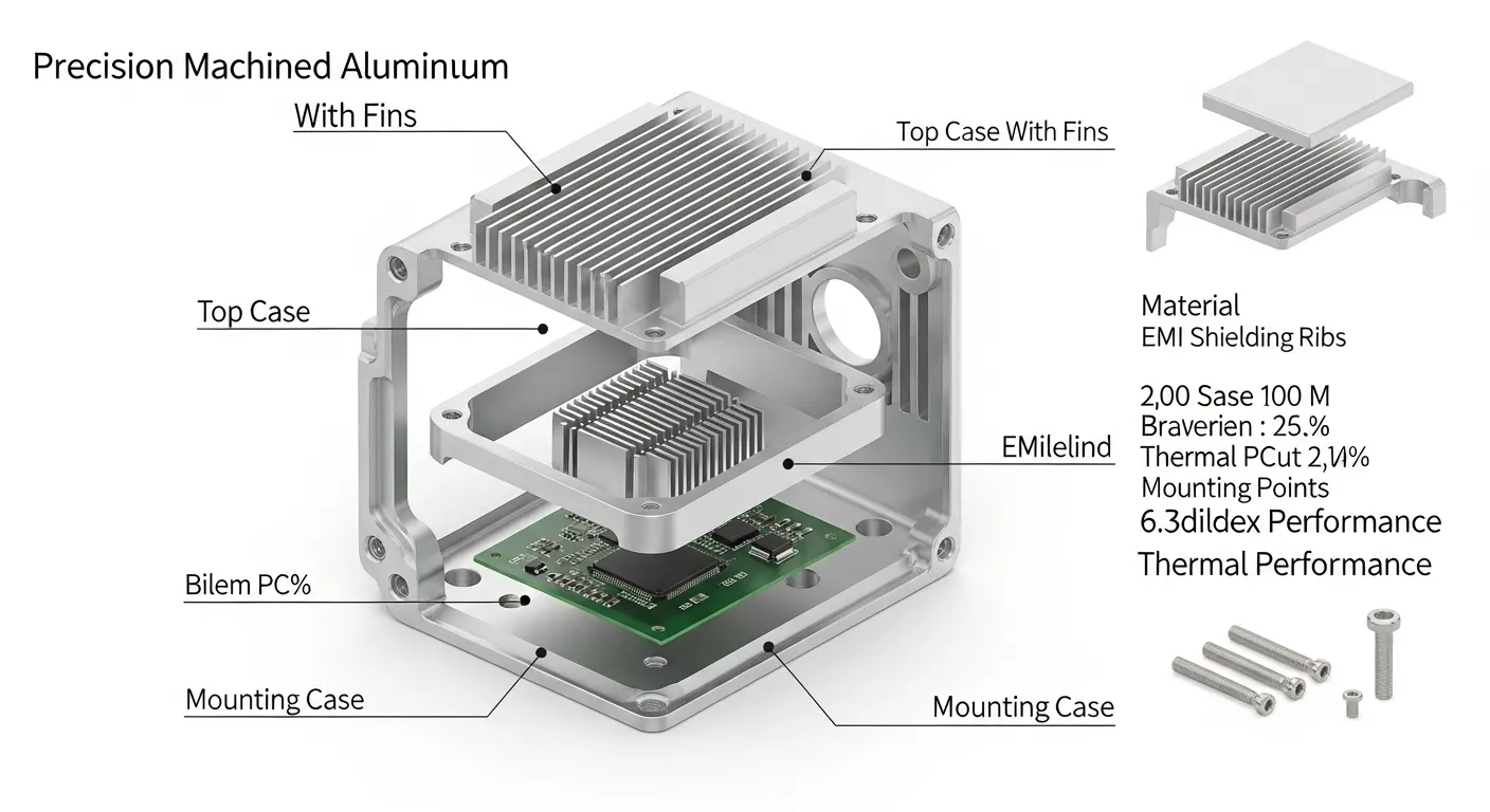
O cliente precisava 200 aluminum enclosures for a new power management module. Their previous supplier had scrapped 18% of parts due to thin-wall deformation on 0.8mm walls. The enclosures needed EMI shielding slots, M3 threaded inserts, and a 12-fin heat sink profile — all machined from a single billet. No welding. No assembly joints.
This is the kind of project where electronics CNC machined parts either prove their value or fall apart. We'll walk through exactly how we solved it.
Visão Geral do Projeto
| Field | Detalhe |
|---|---|
| Client Industry | Eletrônicos de consumo (power management modules) |
| Nome da peça | Aluminum EMI-Shielded Electronic Enclosure |
| Aplicação | Power management unit housing with integrated heat dissipation |
| Região | South Korea OEM (prototyping partner in China) |
| Tamanho do lote | 200 Unidades (pilot production run) |
| Delivery Deadline | 10 Dias úteis |
The client's engineering team had already burned two weeks at a previous supplier. Their DFM report flagged three risks: thin-wall collapse on the 0.8mm EMI shield walls, chatter on the 12-fin array (fin pitch: 3.2milímetro), and incorrect thread depths on M3 inserts. Eles vieram paraPrototipagem GD after seeing our Biblioteca de caixas de usinagem CNC.
Especificações Técnicas
| Parâmetro | Especificação |
|---|---|
| Material | Alumínio 6061-T6 (per ASTM B209) |
| Dimensões da Peça | 120mm x 85mm x 22mm |
| Thin Wall Thickness | 0.8milímetro (EMI shield ribs) |
| Heat Sink Fins | 12 fins, 3.2mm pitch, 14mm height |
| Tolerância Crítica | ±0,01mm (bore fits, mating surfaces) |
| Tolerância Geral | ±0,05mm |
| Acabamento de Superfície | Ra 0.8 μm (Externo); Ra 1.6 μm (internal cavities) |
| Pós-Processamento | Anodize Tipo II (claro), M3 thread inserts x 8 |
| Quantidade | 200 Unidades |
| Tempo de espera | 9 Dias úteis (delivered) |
| Processo Primário | 5-Fregueira CNC no eixo |
| Processo Secundário | Torneamento CNC (Recursos do chefe), Inspeção da CMM |
Aluminum 6061-T6 is the standard choice for electronics enclosures because it combines a tensile strength of 310 MPa with excellent machinability and natural thermal conductivity of ~167 W/m·K.
Processo de usinagem
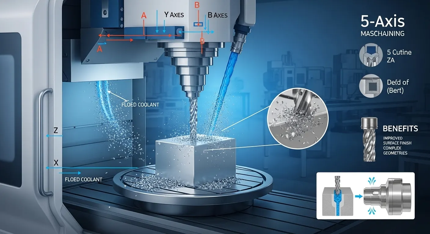
We broke the project into 6 defined stages to control quality at each step.
Palco 1: CAM Programming and DFM Review
Before we cut a single chip, our CAM engineer ran a full DFM check in Mastercam 2026. We flagged two potential failure zones immediately:
- The 0.8mm EMI rib walls risked deflecting under standard side-milling pressure
- The 14mm-tall heat sink fins had a 4.4:1 aspect ratio, which is at the edge of chatter risk
We redesigned the toolpath to use a trochoidal milling strategy on the fins and a climb-milling pass on the thin ribs at reduced radial engagement (8% Passo para o lado).
Palco 2: Fixturing and Setup
We fixtured all billets on a custom zero-point clamping plate. This let us flip each part for Op-2 without re-indicating — critical for holding the ±0.01mm bore position tolerance across both sides.
Palco 3: Rugosidade
Máquina: DMG Mori DMU 50 (5-eixo)
Tool: 10mm 4-flute carbide end mill (TiAlN coated)
Material removal: ~62% of billet volume
Strategy: Adaptive roughing, 6mm axial depth, 35% Engajamento radial
Líquido de arrefecimento: Flood coolant (emulsion, 8% concentration)
Deixamos o material de 0,3mm em todas as paredes para a passagem de acabamento.
Palco 4: Semi-Finalização e Finalização
Tool change to a 4mm 4-flute ball-nose end mill for the fin array. Spindle speed: 18,000 RPM. Feed rate: 1,800 mm/min. We reduced axial depth of cut to 0.15mm for the final finishing pass on all critical bore surfaces. Surface roughness measured Ra 0.76 µm average — inside the Ra 0.8 especificação μm.
Palco 5: Thread Milling
M3 threads were cut using a solid carbide thread mill on the CNC center. Thread depth: 6milímetro (2x diameter — standard for aluminum per ISO 965-1). We avoided tapping to eliminate the risk of tap breakage in blind holes.
Palco 6: Deburring and Post-Processing
Manual deburring with precision files, followed by ultrasonic cleaning. Todos 200 parts then went to our anodizing partner for Type II clear anodize (coating thickness: 10–15 µm per MIL-A-8625).
Desafios e Soluções
Desafio 1: Thin-Wall Deformation on EMI Ribs (0.8milímetro)
This was the reason the previous supplier scrapped 18% de partes. When you machine a 0.8mm wall with a standard side-milling pass, cutting pressure deflects the wall by 0.04–0.06mm — which pushes you outside a ±0.01mm tolerance immediately.
Our first attempt failed too. On the first trial part, we used a 6mm end mill with 25% Engajamento radial. The wall measured 0.83mm on one side and 0.76mm on the other — both out of spec.
Corrigir: We switched to a 3mm 2-flute carbide end mill and reduced radial engagement to 8%. We also changed the machining direction to climb milling with a full-depth single pass. Wall thickness on the second trial part measured 0.79mm–0.81mm — within tolerance across all 12 Costelas.
Desafio 2: Fin Chatter on the Heat Sink Array
Fins at 14mm tall with a 3.2mm pitch have almost no lateral stiffness. At our initial feed rate of 2,400 mm/min, we got visible chatter marks at the fin tips — Ra measured 3.1 µm instead of the 1.6 µm target.
Corrigir: We dropped the feed rate to 1,800 mm/min and switched to a trochoidal toolpath to spread the cutting load. We also added a wax support fill into the fin gaps before the finishing pass, which damped vibration during the final cut. Após a usinagem, the wax dissolved in our ultrasonic cleaning bath. Fin surface finish improved to Ra 1.4 µm — inside specification.
Desafio 3: Thread Insert Depth Consistency
The M3 inserts needed to sit flush ±0.1mm below the part surface. Manual tapping produced inconsistent depths across a 200-part run. On our first full-batch trial, 14 de 50 parts had inserts sitting 0.15–0.2mm proud of the surface.
Corrigir: We programmed all 8 thread positions as a rigid tapping cycle with a programmed Z-stop tied to the part zero datum. Final insert depth across 200 Partes: all within ±0.05mm.
Controle de Qualidade
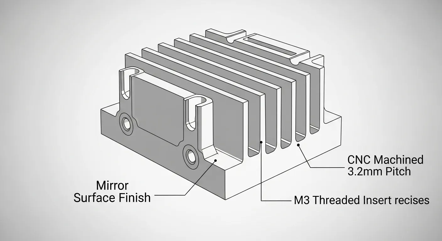
Every part went through a three-stage inspection process before packing.
In-Process CMM Checks
We ran CMM spot-checks every 25 parts using a Zeiss Contura G2 coordinate measuring machine. We checked:
- Bore diameter and position (Crítico: ±0,01mm)
- Espessura da parede (todos 12 EMI ribs)
- Thread depth and position
- Overall envelope dimensions
Surface Roughness Verification
We used a Mitutoyo SJ-410 profilometer on 100% of parts for the external mating face (Ra spec: 0.8 μm) and a 10% sample on internal cavities (Ra spec: 1.6 μm).
Final Dimensional Report
Todos 200 parts received a full measurement report. We documented Cpk values for the three tightest tolerances:
- Diâmetro do diâmetro do diâmetro: Cpk = 1.47
- Espessura da parede (EMI ribs): Cpk = 1.31
- Thread depth: Cpk = 1.68
A Cpk above 1.33 indicates a process that is capable and stable.
Resultados
The numbers tell the story directly:
- Entrega: 200 Peças entregues em 9 Dias úteis (1 Dia antes do cronograma)
- Rendimento na primeira passagem: 199/200 parts passed all inspection criteria (99.5%)
- Peças rejeitadas: 1 parte (fin surface roughness Ra 1.7 µm on a single fin — caught in-house, not shipped)
- Taxa de sucata: 0.5% Vs. 18% at the client's previous supplier
- Desempenho térmico: Client's engineering team reported 11°C lower junction temperature in assembled modules vs. the previous cast housing design
- EMI shielding: Todos 200 units passed client's EMI pre-compliance scan at 300 MHz–1 GHz
The client approved a second batch of 1,500 unidades dentro 3 weeks of receiving the pilot run.
Por que a usinagem CNC foi usada
The client initially considered two alternatives: die casting and metal 3D printing (DMLS). Here's why both failed the brief:
| Fator | O Elenco | DMLS (Metal 3D Print) | Usinagem CNC |
|---|---|---|---|
| Espessura da parede (0.8milímetro) | Not feasible below ~1.5mm | Possible but rough surface | Achievable with correct toolpath |
| Acabamento superficial | Ra 1,6–3,2 μm (Como elenco) | Ra 6–15 µm (as-built) | Ra 0.8 μm (terminado) |
| Tolerâncias | ±0.2–0.5mm | ±0,1–0,2mm | ±0,01mm |
| Prazo de entrega (200 Pcs) | 4–6 semanas (tooling required) | 12–15 days | 9 Dias |
| Custar (200 Pcs) | Alto (Ferramenta amortizada) | Muito alto | Moderado |
Die casting requires hard tooling — typically 4–6 weeks and $8,000–$15,000 in mold cost for a part this size. For a 200-unit pilot, that cost cannot be amortized. DMLS could produce the geometry but couldn't hit the Ra 0.8 µm surface finish or the ±0.01mm bore tolerance without extensive secondary machining — which would add both time and cost.
CNC machining from 6061-T6 billet was the only method that hit all three requirements: tolerância, Acabamento superficial, and 10-day lead time without tooling investment. You can explore GD Prototyping's full Serviços de usinagem CNC for more on our process capabilities.
Perguntas Freqüentes
Aluminum 6061-T6 is the most common choice. It machines cleanly, dissipates heat well (~167 W/m·K), and accepts anodize coatings for EMI control. For higher-strength applications, 7075-T6 is an option. For non-conductive requirements, PEEK or Delrin are viable plastics.
On a 5-axis machining center with proper fixturing, we routinely hold ±0.01mm on critical bore fits and ±0.05mm on general dimensions. GD Prototyping's standard tolerance is ±0.05mm, with tighter tolerances available on request for critical features.
For a part like this one — 120mm x 85mm x 22mm with complex features — cycle time per part runs approximately 18–24 minutes on a 5-axis machine. With a two-machine cell running in parallel, a 200-part run can be completed in 7–8 machining days, plus 1–2 days for inspection and post-processing.
Sim, especially for pilot runs and low-to-medium volumes (under 2,000 Unidades). CNC machining needs no tooling investment, holds tighter tolerances, and delivers better surface finish than as-cast die casting. For volumes above 5,000 Unidades, die casting becomes more cost-effective per part.
Upload your STEP or IGES file to GD Prototyping's quoting system. Include your material spec, Requisitos de tolerância, Acabamento superficial, Quantidade, and deadline. You'll receive a detailed quote with DFM feedback within 12 Horas.
Conclusão
Electronics CNC machined parts demand more than a fast quote and a CNC machine. They need a team that understands thin-wall dynamics, thermal management requirements, and the tolerance stack-ups that separate a working prototype from a scrapped batch.
Nós entregamos 200 precision aluminum enclosures in 9 Dias, com um 99.5% first-pass yield and zero field returns from the client's EMI pre-compliance testing.
If your electronics project needs tight tolerances, Geometrias complexas, or a supplier that actually understands your DFM risks — contate GD Prototipagem Hoje. Upload your file and get a quote with DFM feedback in under 12 Horas.
You can also browse our Estudos de caso de usinagem CNC to see more examples like this one.
