


CNC Machining Service for Stainless Steel Parts: How We Held ±0.02mm on 150 Structural Brackets for a European Fluid Control System
A European industrial equipment OEM needed 150 stainless steel 316L fluid control brackets machined to ±0.02mm tolerance with Ra 0.8 µm surface finish in 12 days. We used 5-axis CNC milling on a DMG Mori DMU 50 with TiAlN-coated carbide tooling. All 150 parts passed CMM inspection. On-time delivery: 100%.
Introduction
The client sent us a drawing that made our engineers pause for a second look.
It was a stainless steel 316L structural bracket for a high-pressure fluid control manifold. The part had a 1.8mm thin wall section, a deep internal channel at 38mm depth, and a bilateral tolerance of ±0.02mm on the mating bore. The quantity was 150 units. The deadline was 12 working days.
This is the kind of CNC machining service for stainless steel parts that separates a reliable supplier from a generic job shop. Stainless steel 316L work-hardens fast. One wrong pass and you've scrapped a part that took 47 minutes to rough out. We've run projects like this before, and this write-up documents exactly what we did, what failed on the first attempt, and how we delivered every part on spec.
Project Overview
The client was a mid-sized German industrial equipment manufacturer producing fluid control systems for the pharmaceutical processing sector. Their end product operates under 120 bar pressure and must pass FDA facility compliance audits, which demands zero dimensional deviation at mating interfaces.
They needed a batch of 150 stainless steel brackets to replace a cast version that had shown porosity defects in QC. Casting was off the table. The new design required a machined part with clean internal channels, a tight bore, and a corrosion-resistant surface finish that could handle regular CIP (clean-in-place) chemical wash cycles.
We were given 3D STEP files, a 2D drawing with GD&T callouts, and a 12-day lead time window. The project went live the next morning.
Technical Specifications
| Parameter | Value |
|---|---|
| Material | Stainless Steel 316L |
| Part Name | Fluid Control Bracket |
| Dimensions | 142mm x 88mm x 56mm |
| Wall Thickness (min) | 1.8mm |
| Tolerance | ±0.02mm (bore), ±0.05mm (general) |
| Surface Finish | Ra 0.8 µm (mating faces), Ra 1.6 µm (general) |
| Internal Channel Depth | 38mm |
| Quantity | 150 units |
| Lead Time | 12 working days |
| Machines Used | DMG Mori DMU 50 (5-axis), Haas ST-10 (turning) |
| Process | 5-axis CNC milling, CNC turning, deburring, electropolishing |
| Inspection | CMM (Zeiss Contura), surface profilometer |
Machining Process
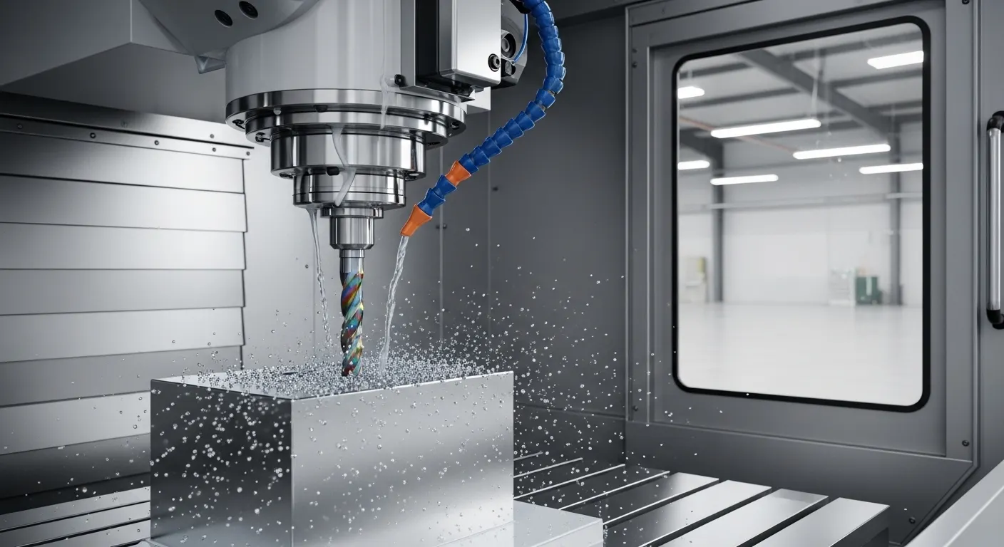
We broke the job into five clear stages. Each stage had a defined checkpoint before the next began.
Stage 1: CAM Programming
Our CAM engineer programmed the part in Mastercam X9. We ran a full material removal simulation first to spot any potential tool-path collisions in the deep channel area. The simulation flagged a clearance issue at the 38mm depth, so we added a custom extended-reach carbide end mill to the tool library before cutting a single chip.
Stage 2: Workholding Setup
We designed a bespoke soft-jaw fixture to hold the 316L billet on the DMG Mori DMU 50. The fixture used four-point contact clamping to avoid distorting the thin wall section during roughing. Correct workholding was critical here because 316L has low thermal conductivity. If the part can't dissipate heat properly, it work-hardens and tolerances drift.
Stage 3: Roughing
We used a 10mm 4-flute TiAlN-coated carbide end mill running at 2,800 RPM with a feed rate of 380mm/min. We kept the axial depth of cut to 1.5mm in roughing to avoid triggering work hardening. Coolant flood was set at full pressure throughout. We left 0.3mm stock on all surfaces for the finishing pass.
Stage 4: Finishing
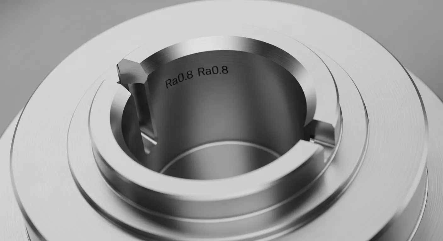
The finishing pass used a 6mm 3-flute carbide ball-nose end mill at 4,200 RPM. We brought the feed rate down to 180mm/min for the bore and internal channel. The step-over on the mating surfaces was set at 0.08mm to achieve the Ra 0.8 µm finish without additional grinding.
Stage 5: Electropolishing
After machining and deburring, all 150 parts went through a 12-minute electropolishing cycle. This removed the micro-burrs inside the internal channels and improved the corrosion resistance of the 316L surface, which was a direct requirement from the client's pharmaceutical compliance team.
Challenges and Solutions
Challenge 1: Thin-Wall Deformation at 1.8mm
On the first test batch of three parts, we saw a 0.06mm bow on the 1.8mm wall after roughing. The wall was deflecting under cutting pressure, pushing it out of tolerance. This was the failed attempt.
Fix: We added a custom-machined support block inside the pocket during the roughing stage. It was a simple sacrificial aluminum insert that braced the thin wall from the inside. We also reduced the radial depth of cut from 4mm to 2mm and dropped the feed rate to 280mm/min on the thin-wall passes. After these changes, the wall bow measured 0.008mm on all three re-run test parts. We locked in those parameters for the full batch.
Challenge 2: Tolerance Drift on the Mating Bore
The ±0.02mm bore tolerance required consistent thermal stability. In our first 20-part run, parts 17-20 showed bore diameters 0.025mm over the upper limit. The machine's spindle had thermally expanded after 6+ hours of continuous operation.
Fix: We implemented a 15-minute spindle warm-up protocol before every shift start and added a mid-batch spindle compensation check at every 25-part interval. We also used a bore gauge to spot-check every 10th part during production. After the fix, all remaining 130 parts measured within ±0.016mm on the bore, well inside the ±0.02mm callout.
Challenge 3: Deep Channel Tool Reach
The 38mm deep internal channel needed a small-diameter cutter to reach the floor radius. Standard tooling with a 3xD reach caused chatter vibration at depth, which left visible tool marks.
Fix: We switched to a 6mm diameter extended-reach end mill with a 42mm flute length and applied a reduced feed rate of 120mm/min at depth. We also programmed a helical entry path to reduce the initial cutting impact. The chatter disappeared completely, and the channel surface measured Ra 1.4 µm consistently.
Quality Control
Every part went through a three-level inspection process before it was packed.
Level 1: In-Process Gauging
We checked bore diameter every 10 parts using a calibrated Mitutoyo bore gauge. Any reading outside ±0.018mm triggered a machine stop and parameter review.
Level 2: CMM Inspection
A 10% sample (15 parts) from each production batch went to our Zeiss Contura CMM. We measured 14 critical dimensions per part, including bore diameter, flatness of mating faces, position of the channel floor, and perpendicularity of the mounting holes. All 15 sampled parts in every batch passed on the first measurement.
Level 3: Surface Profilometry
We used a Mitutoyo SJ-410 surface profilometer on the Ra 0.8 µm mating faces. Every batch had three random parts checked. All readings fell between Ra 0.62 µm and Ra 0.79 µm.
All 150 parts shipped with a full dimensional report and material certificate (EN 10204 3.1) as required by the client.
We follow ISO 9001:2015 quality management principles across all production and inspection stages.
Results
- Delivery time: 11 working days (1 day ahead of the 12-day deadline)
- First-pass yield: 148 of 150 parts passed CMM on first measurement (98.7%)
- Rework rate: 2 parts required minor bore re-finishing (1.3%), both passed on second check
- Scrap rate: 0%
- Surface finish pass rate: 100% on all profilometry checks
- Client feedback: The brackets were fitted directly into the manifold assembly without any on-site rework, which was the primary success metric for the project
- Follow-on order: The client placed a repeat order for 300 units within 18 days of delivery
Why CNC Machining Was the Right Choice
The client had used investment casting for the previous version of this bracket. The cast parts had internal porosity, which created micro-leaks under 120 bar pressure. Casting also couldn't hold the ±0.02mm bore tolerance without a secondary machining step, adding cost and time.
3D printing in 316L (DMLS) was evaluated but ruled out for two reasons: the internal channel geometry required post-process EDM finishing to meet the Ra 0.8 µm requirement, and the per-part cost was 2.4x higher than CNC machining at this quantity.
CNC machining from solid 316L bar stock delivered three things that neither casting nor 3D printing could match simultaneously: zero porosity, direct tolerance achievement without secondary operations, and a cost-effective unit price at 150-part volume.
You can see how we handle similar projects on our CNC machining case studies page, which includes work across metals, plastics, and complex geometries. Our CNC machining services cover 3-axis through full 5-axis milling with ±0.05mm standard tolerance and Ra 0.2 µm surface capability.
For tight-tolerance stainless work specifically, 5-axis CNC milling is almost always the better path when tolerances are tighter than ±0.05mm or when the part has internal features that a 3-axis machine can't reach cleanly.
FAQ
We regularly machine 303, 304, 316, and 316L. For medical and pharmaceutical applications, 316L is the most common choice because of its low carbon content, which reduces sensitization risk during welding and chemical exposure. We can also work with 17-4 PH, 440C, and duplex grades on request.
Our standard CNC machining service for stainless steel parts holds ±0.05mm. For critical features like bores or mating faces, we can achieve ±0.01mm with dedicated fixturing and in-process gauging, as we did on the fluid control bracket project above.
We use sharp TiAlN-coated carbide tooling, keep cutting depths light (1.5mm axial in roughing), maintain full coolant flood pressure, and avoid dwelling the cutter in the cut. Dwelling even for a fraction of a second in 316L causes work hardening and kills your tool life fast.
We offer as-machined (Ra 1.6-3.2 µm), precision-finished (Ra 0.8 µm), electropolishing, passivation (per ASTM A967), glass bead blasting, and mirror polishing. Electropolishing is the most popular for pharmaceutical and food-grade applications because it also improves the corrosion resistance of the 316L base material.
There's no minimum. We run single prototypes and batches of 1,000+ using the same machines and inspection process. For prototypes, lead times start at 3 working days. For production runs like the 150-part project above, we typically deliver in 10-15 working days depending on complexity.
Conclusion
This project showed exactly what a reliable CNC machining service for stainless steel parts looks like in practice: tight tolerances held across a full 150-part run, a thin-wall deformation problem caught and fixed before it hit the full batch, and on-time delivery with a full dimensional report.
If you're working on stainless steel parts with tight tolerances, complex internal features, or pharmaceutical/industrial compliance requirements, we want to see your drawings.
Contact GD Prototyping for a free quote. Upload your STEP file and 2D drawing, and our engineers will review your project and respond within 12 hours with a detailed machining plan and price.
Explore more of our work:
- CNC Machining Case Studies — real projects across metals and plastics
- CNC Machining Services Overview — capabilities, tolerances, and materials
