


CNC Machining Service for Aluminum Parts
For this cnc machining service for aluminum parts project, we machined 180 sensor housings from Aluminum 6061-T6 at 168 × 94 × 42 mm, with 1.8 mm wall sections, ±0.02 mm critical tolerances, and 15 μm clear anodizing. We used 5-axis milling, vacuum fixturing, in-process probing, CMM inspection, and bead blasting. The batch shipped in 9 working days, reached a 98.3% first-pass rate, and hit 100% final delivery.
Introduction
This cnc machining service for aluminum parts started with a hard deadline of 12 working days and a housing that had already failed in plastic. The client’s first ABS prototype warped by 0.18 mm at 65°C, and the gasket groove lost seal compression after 3 thermal cycles.
We were asked to replace that prototype with 180 production-like aluminum housings for a German warehouse automation program. Because the part had to move fast from test to bridge production, we built the workflow around GD’s CNC machining services, the available materials, and the brand’s own CNC machining case studies.
Project Overview
The client was a European automation equipment maker building LiDAR sensor modules for autonomous mobile robots. Each housing had to protect a 48V control board, hold a lens mount within ±0.02 mm, and keep total weight under 200 g for a 14-hour battery shift.
We chose Aluminum 6061-T6 because the housing needed a good balance of machinability, corrosion resistance, thread strength, and stable anodizing. The final part weighed 186 g, used a 68 mm deep internal pocket, and included 24 threaded features, 1 sealing groove, and 2 datum bores.
The job sat between prototype and production, not fully mass volume. That made it a strong fit for the kind of bridge work shown on GD’s CNC machined aluminum parts and CNC machined anodized aluminum pages.
Technical Specifications
| Item | Specification |
|---|---|
| Material | Aluminum 6061-T6 |
| Part name | LiDAR sensor housing |
| Dimensions | 168 × 94 × 42 mm |
| Wall thickness | 1.8 mm minimum |
| Deep cavity | 68 mm |
| Critical tolerances | ±0.02 mm on datum bores and lens seat |
| General tolerances | ±0.05 mm |
| Flatness | 0.03 mm on sealing face |
| Surface finish | Bead blasted + clear anodized, 15 μm |
| Surface roughness | Ra 1.6 μm external, Ra 3.2 μm internal pocket |
| Quantity | 180 pcs |
| Lead time | 9 working days |
| Process | 5-axis CNC milling, drilling, tapping, deburring, bead blasting, anodizing |
Machining Process for This CNC Machining Service for Aluminum Parts
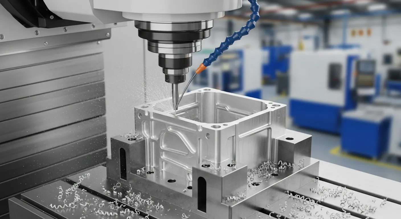
We started from 172 × 98 × 46 mm 6061-T6 saw-cut blanks and built the CAM program in Fusion 360 with 3 setups. The roughing stock allowance was 0.35 mm on walls and 0.20 mm on sealing faces to control movement before final finishing.
For Op 1, we roughed the outside profile and top features on a Haas VF-2SS using a 12 mm carbide end mill at 12,000 rpm and 2.8 mm axial stepdown. We drilled 10 pilot holes, milled the gasket groove to 1.25 mm depth, and left the lens seat oversize by 0.15 mm.
For Op 2, we moved the part to a DMG Mori DMU 50 5-axis machine for the 68 mm cavity, side ports, and datum bores. We used a 6 mm long-neck tool for the deep pocket, a 3 mm end mill for corner cleanup, and spindle probing before every critical finish pass.
For Op 3, we ran deburring, bead blasting, and clear anodizing at 15 μm nominal thickness. The finish path followed the same logic shown in GD’s aluminum-focused examples, especially the CNC machined anodized aluminum work, where aluminum precision and post-finish appearance both matter.
Challenges and Solutions
1. Thin wall deformation at 1.8 mm
Our first trial part failed. We clamped the blank in a standard vise, machined the 68 mm cavity too early, and measured wall bow of 0.12 mm on the long side. The sealing face flatness also drifted from 0.03 mm target to 0.16 mm.
We fixed it by changing 3 things. First, we left 0.35 mm stock on thin walls during roughing. Second, we switched to custom soft jaws plus vacuum support under the cavity floor. Third, we split finishing into semi-finish, 6-hour rest, and final skim passes of 0.15 mm radial engagement. The next 5 samples stayed within 0.028 mm wall movement.
2. Deep cavity chatter at 68 mm depth
The first long-reach toolpath left visible chatter lines and an internal surface of Ra 3.4 μm. On one corner, tool deflection pushed the radius out by 0.06 mm, which was too much for the internal PCB stand-off clearance.
We shortened tool stick-out from 72 mm to 58 mm by rotating the part on the 5-axis trunnion and attacking the wall at a better angle. We also changed from a slotting path to trochoidal roughing with 8% radial engagement. That dropped chatter, brought the corner error down to 0.012 mm, and improved the internal finish to Ra 2.1 μm.
3. Tight hole position across a long datum chain
The lid screw pattern had to hold true position within 0.03 mm across a 142 mm span. In our first 2-setup test, the opposite corner holes drifted by 0.07 mm because the second setup stacked too much datum error.
We solved that by moving all critical holes into one 5-axis setup and using in-machine probing on 2 datum bores before final drilling and tapping. After that change, the average positional error across 12 checked housings was 0.014 mm.
Quality Control
We checked first-article parts on a Zeiss CMM using 18 measured features, including the 2 datum bores, lens seat diameter, sealing face flatness, and hole pattern true position. We also used thread gauges for 24 threaded features, a Mitutoyo surface tester for Ra checks, and an eddy current gauge to confirm anodizing thickness between 13 μm and 17 μm.
For drawing control, we used ±0.05 mm as the general machining baseline and tightened only the functional features to ±0.02 mm or 0.03 mm flatness. That matches the common use of ISO 2768-1 as a framework for general linear and angular tolerances when every dimension is not individually toleranced.
Results
We shipped the first 30 housings in 7 working days and the full 180-piece batch in 9 working days. The client had requested 12 working days, so we finished 3 days early.
Here are the key numbers:
- First-pass machining yield: 98.3% or 177 of 180 parts
- Final shipment acceptance: 100%
- Average CMM deviation on critical bores: 0.011 mm
- Sealing face flatness average: 0.021 mm
- Housing weight: 186 g, below the 200 g target
- Assembly time at the client side: 22% faster than the plastic prototype
- Thermal test result: internal electronics ran 6.8°C cooler than the ABS housing version
The client approved a second bridge order for 420 pcs after the first batch passed vibration testing at 20 g and a 96-hour salt spray review on the anodized finish.
Why CNC Machining Was Used for These Aluminum Parts
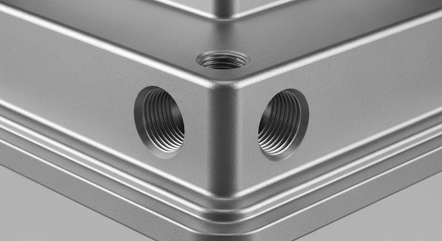
We used CNC instead of die casting because the volume was only 180 pcs and the design was still moving. A die-cast route would likely need tooling, extra approval time, and at least 4 to 6 weeks before first articles. CNC let us cut rev A, revise the cable port after part 24, and ship rev B without new tooling.
We also ruled out polymer 3D printing because the earlier ABS sample had already warped by 0.18 mm at 65°C, and the screw bosses stripped after repeated service access. Aluminum 6061-T6 gave us better thread life, cleaner sealing faces, and much better thermal behavior.
Material choice also mattered. The Aluminum Association describes 6xxx alloys as heat-treatable, formable, weldable, and corrosion resistant, with 6061 called the most widely used alloy in that family. That made 6061-T6 the right balance for a lightweight housing that still needed stable machining and anodizing.
FAQ: CNC Machining Service for Aluminum Parts
For most housings and brackets, we start with 6061-T6. It gives a good mix of strength, corrosion resistance, cost, and machinability. For this 168 × 94 × 42 mm housing, 6061-T6 also gave stable threads and clean anodizing after bead blasting.
For standard features, we usually plan around ±0.05 mm. For critical bores, sealing lands, and mating features, we can tighten that to ±0.02 mm or even lower with better fixturing, probing, and CMM validation. In this case, our measured bore deviation averaged 0.011 mm.
Yes, but the wall strategy matters. On this job, the 1.8 mm wall bowed by 0.12 mm in the first trial. We fixed that with stock allowance, vacuum support, and staged finishing, then kept movement below 0.028 mm in the approved process.
That depends on use. For this robot housing, we used bead blasting plus 15 μm clear anodizing because it improved corrosion resistance, gave a uniform matte look, and protected handling surfaces. If appearance matters more, color anodizing or polishing can also work well.
Choose CNC when you need 1 to 500 parts, fast design changes, no tooling cost, or tighter feature control on early batches. For this 180-piece bridge order, CNC beat casting because we delivered in 9 working days and updated the port geometry mid-run without new tooling.
Conclusion + CTA
This project shows what a real cnc machining service for aluminum parts should do: hold ±0.02 mm where it matters, solve deformation before it hits production, and ship low-volume parts fast enough for a live program. We machined 180 anodized 6061-T6 housings in 9 working days, improved thermal performance by 6.8°C, and gave the client a bridge batch that behaved like production parts.
If you’re building aluminum housings, brackets, covers, or custom functional parts, review GD’s CNC machining case studies and then contact us with your drawing, quantity, and tolerance stack.
