
CNC Machining Services for Plastic Functional Prototypes: The Complete Guide
CNC machining is the most reliable method for producing plastic functional prototypes with tight tolerances (±0.01 mm to ±0.05 mm), real engineering-grade material properties, and fast turnaround (3 to 7 days). It works best for 1 to 100 units where design validation, fit testing, or functional performance testing is required before committing to production tooling.
What Are Plastic Functional Prototypes?
A plastic functional prototype is a physical part made from real engineering plastic that performs like the final production component. It is not a visual model or a concept mock-up. It gets tested, assembled, loaded, pressurized, or cycled under real operating conditions.
The keyword "functional" is what separates these parts from display prototypes. Your engineer needs to know:
- Does the part fit the mating assembly?
- Does it hold the required pressure or load?
- Does the material resist the chemicals or temperatures in the application?
- Does it meet FDA, ISO, or industry compliance requirements?
Functional prototypes answer all of those questions before you spend $8,000 to $40,000 on an injection mold.
Why Engineers Choose CNC Machining for Plastic Prototypes
CNC machining for plastic functional prototypes dominates over other processes for one simple reason: it produces parts from the same material and with the same mechanical properties as your final production component.
Here's a direct comparison across the three most common prototyping processes:
| Factor | CNC Machining | FDM / SLS 3D Printing | Injection Molding |
|---|---|---|---|
| Material authenticity | True stock material (e.g., PEEK, Delrin) | Proprietary filament or powder, anisotropic strength | True production material |
| Tolerance | ±0.01 mm to ±0.05 mm | ±0.2 mm to ±0.5 mm typical | ±0.05 mm to ±0.1 mm |
| Surface finish | Ra 0.4 µm to Ra 3.2 µm | Ra 5 to Ra 15 µm (layer lines) | Ra 0.4 µm to Ra 1.6 µm |
| Lead time (10–50 units) | 3 to 7 working days | 1 to 4 days | 4 to 8 weeks (tooling) |
| Tooling cost | $0 | $0 | $8,000 to $40,000+ |
| Unit cost (10–50 units) | Medium | Low to medium | Very high (amortized tooling) |
| Best for | Functional testing, tight fits | Concept, visual, early-stage | Volume production (1,000+) |
The conclusion is clear. For 1 to 100 units that need to be functionally tested, CNC machining delivers the best combination of accuracy, material integrity, and speed.
At GD Prototyping, we run 3-axis, 4-axis, and 5-axis CNC machining centers specifically optimized for engineering plastic work, with lead times starting at 3 working days.
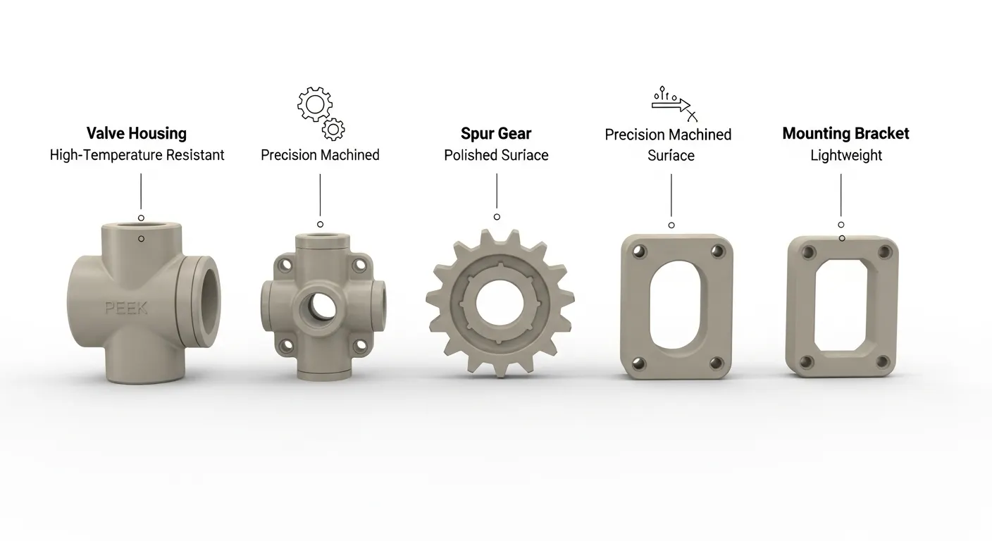
Best Plastics for CNC Functional Prototypes
Not every plastic machines the same way. Choosing the right material is the first engineering decision in any plastic prototype project. Here are the most common materials we machine and when to use each one.
PEEK (Polyether Ether Ketone)
PEEK is the gold standard for high-performance plastic prototypes. It handles continuous temperatures up to 250°C, resists almost all industrial chemicals, and meets ISO 10993-5 biocompatibility requirements for medical devices.
- Tensile strength: 100 MPa
- Continuous service temperature: 250°C
- Best for: Medical devices, aerospace fluid systems, semiconductor equipment
- Machining note: Requires annealing before cutting and dry-air cooling to preserve crystalline structure
Delrin (POM-C / Acetal)
Delrin is the most machinable engineering plastic. It holds tight tolerances extremely well, has a naturally low friction surface, and is chemically resistant to fuels, solvents, and oils.
- Tensile strength: 69 MPa
- Dimensional stability: Excellent (low moisture absorption)
- Best for: Gears, bushings, valve seats, food-contact components
- Machining note: Machines cleanly at high speeds with minimal burring
Nylon (PA6 / PA66)
Nylon offers excellent impact resistance and fatigue strength but absorbs moisture, which can cause dimensional drift. For functional prototypes requiring exact fits, we recommend pre-drying billets and machining to the dry-state dimensions.
- Tensile strength: 75 to 85 MPa
- Best for: Structural brackets, wear components, cable guides
- Machining note: Moisture absorption of up to 2.5% can shift dimensions; critical fits must account for this
Polycarbonate (PC)
PC is optically clear, tough, and holds good tolerances. It's widely used for enclosures, light guides, and housings that need visual inspection or light transmission.
- Tensile strength: 55 to 65 MPa
- Best for: Optical housings, electrical enclosures, safety shields
- Machining note: Susceptible to stress cracking near sharp internal corners; generous radii required
PTFE (Teflon)
PTFE has the lowest friction coefficient of any engineering plastic and outstanding chemical resistance. It's soft and creeps under load, so it's not suited for structural parts but is ideal for seals, liners, and chemical contact components.
- Best for: Valve seats, chemical seals, bearing liners
- Machining note: Requires sharp tooling and careful fixturing; it deforms under clamping pressure
UHMW-PE
Ultra-high molecular weight polyethylene is extremely wear-resistant and impact-resistant. It's commonly used in conveying, food processing, and marine applications.
- Best for: Wear pads, conveyor components, cutting boards, marine bushings
- Machining note: Stringy chips; requires chip-breaking tool geometry and frequent evacuation
Tolerances You Can Expect from CNC Plastic Machining
Tolerance capability in plastic CNC machining depends on three factors: material stability, part geometry, and fixturing method. Here's what you can realistically expect:
| Tolerance Class | Value | Achievable On |
|---|---|---|
| General machining | ±0.05 mm | External profiles, non-critical holes |
| Precision machining | ±0.02 mm | Bores, mating surfaces, shaft fits |
| High precision | ±0.01 mm | Optical seats, precision valve bores |
| Angular tolerance | ±0.1° to ±0.5° | Radial features, indexed holes |
One thing most guides don't tell you: plastics respond to temperature changes. PEEK has a thermal expansion coefficient of approximately 47 µm/m·°C. On a 100 mm part, a 10°C workshop temperature change creates a 0.047 mm dimensional shift. Our shop maintains temperature at 20°C ±1°C during final machining and CMM inspection of precision parts, which is why we consistently hit ±0.02 mm on plastic bores.
The CNC Machining Process for Plastic Functional Prototypes
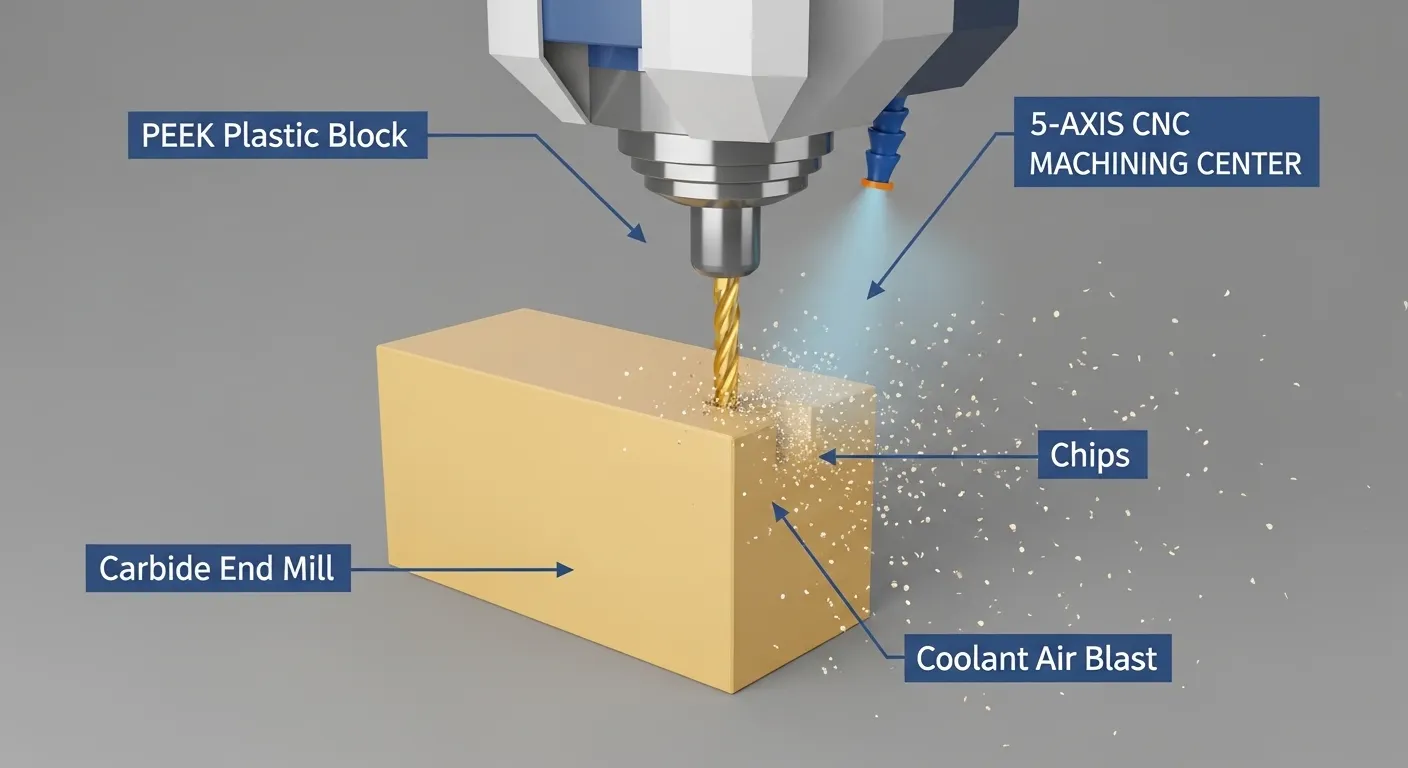
Understanding the step-by-step process helps you communicate better with your machining partner and design parts that are easier (and cheaper) to produce.
Step 1: DFM Review (Design for Manufacturability)
Before any cutting starts, our engineers review your STEP or IGES file for features that will cause problems. Common DFM issues in plastic prototypes include:
- Internal corners with a radius smaller than the tool radius
- Wall sections thinner than 0.8 mm without support geometry
- Deep cavities with length-to-diameter ratios above 6:1
- Thread call-outs without runout relief
A DFM review on a typical plastic prototype takes 1 to 4 hours. It often saves 1 to 2 days of machining rework later.
Step 2: Material Preparation
For stress-sensitive plastics like PEEK and Nylon, we anneal the billet stock before cutting. For PEEK, this means 4 hours at 200°C in a calibrated oven. This removes residual stress from the extrusion process, which if left untreated causes the part to spring or warp after roughing.
Step 3: CAM Programming
We use Mastercam for toolpath generation. The main decisions at this stage are:
- Roughing strategy (adaptive clearing vs. traditional pocketing)
- Tool selection (number of flutes, coating, stick-out length)
- Finishing path (climb milling vs. conventional milling)
- Coolant strategy (air blast, MQL, or dry depending on material)
For thin-wall sections, we model support strategies directly in the CAM file. For deep bores, we program peck-drilling cycles with full retract for chip evacuation.
Step 4: Roughing Pass
A roughing pass removes 90 to 95% of the raw material quickly. We use larger diameter end mills at high feed rates and leave 0.2 to 0.4 mm of stock on all critical surfaces.
Chip color and temperature are the key diagnostics at this stage. Ideal chips from PEEK are straw-yellow and curl freely. Dark or discolored chips indicate excessive heat — a sign that spindle speed or feed rate needs adjustment.
Step 5: Semi-Finishing and Finishing
The finishing pass removes that last 0.2 to 0.4 mm of stock using smaller tools, slower feed rates, and higher spindle speeds. This is where tolerance and surface finish are determined.
For 5-axis features like radial ports or complex profiles, we complete all finishing in a single clamping whenever possible. Every re-clamp on a precision plastic part introduces at least 0.01 to 0.03 mm of repositioning error. One setup, one chance for error.
Step 6: Deburring and Cleaning
Plastic parts get deburred manually with plastic-safe scrapers and brushes. No metal files, which can embed particles. For medical or semiconductor parts, we follow with 20-minute ultrasonic cleaning in deionized water.
Challenges in CNC Machining Plastic Functional Prototypes
Plastic is not just "easier metal." It has its own failure modes. Here are the four most common challenges and how we solve them.
Challenge 1: Thin Wall Vibration and Deformation
Walls thinner than 2.0 mm vibrate during cutting. This causes chatter, poor surface finish, and dimensional error. Standard solution: reduce feed rate. But with plastics, slower cutting increases heat dwell time, which causes thermal deformation.
Our preferred fix for walls below 1.5 mm is custom pneumatic or foam-backed fixtures that support the wall from the opposite side during the final finishing pass. This eliminates chatter without increasing thermal load.
Challenge 2: Deep Bore Chip Packing
At bore depth-to-diameter ratios above 5:1, chips pack at the bottom and get re-cut. Re-cut chips act as abrasives. Bore finish degrades from Ra 0.8 µm to Ra 3 µm or worse.
Fix: Programmed peck cycles with full retract and timed air blast intervals. We add one full retract every 4 to 5 mm of bore depth. It adds cycle time but keeps the bore finish on spec.
Challenge 3: Stress-Related Warping After Machining
Some plastics — especially Nylon and semi-crystalline grades — warp after machining because cutting releases the internal stresses locked in during material extrusion.
Fix: Anneal before machining. For critical parts, a secondary stress-relief anneal after roughing (before finishing) virtually eliminates post-machining dimensional drift.
Challenge 4: Clamping Deformation
Soft plastics like PTFE and UHMW-PE deform under standard metal vise clamping pressure. The part measures in-tolerance while clamped, springs back out of tolerance when released.
Fix: Custom soft-jaw fixtures machined from aluminum or nylon that distribute clamping force across a large surface area. Clamping torque is set and recorded for consistency across a batch.
Quality Control and Inspection
A CNC-machined plastic prototype is only as good as its inspection process. Here's the three-stage QC protocol we use at GD Prototyping for precision plastic prototypes.
Stage 1: In-Process Gauging
We use Renishaw OMP60 on-machine probing to verify critical dimensions after the roughing pass, before finishing. Parts outside the pre-machining allowance get corrected before we commit to the finish cuts.
Stage 2: CMM Measurement
All precision plastic prototypes are measured on a Hexagon Global CMM in our temperature-controlled (20°C ±1°C) inspection room. We measure:
- All toleranced dimensions per the 2D drawing
- Bore diameter at multiple depth stations
- Flatness, parallelism, and perpendicularity of mating surfaces
- True position of all hole patterns
Stage 3: Surface Roughness Verification
We use a Mitutoyo SJ-410 profilometer on all surfaces with Ra callouts. Inspection certificates with actual measured values ship with every order.
Industries That Use CNC Plastic Prototype Machining
CNC machining services for plastic functional prototypes serve a wide range of industries. Each one has its own material preferences and tolerance requirements.
Medical Devices
PEEK, UHMW-PE, and PTFE dominate here due to biocompatibility and sterilization resistance. Tolerances down to ±0.01 mm are common for surgical instrument components and fluid path components.
Aerospace and Defense
Lightweight, dimensionally stable plastics like PEEK and PVDF replace metals in non-structural aerospace applications. CNC prototypes are used for bracket validation, connector housings, and fluid system components.
Automotive Engineering
Engineers prototype fluid connectors, sensor housings, and interior clips in Nylon, POM, and PC before committing to injection mold tooling. German OEMs frequently use CNC plastic prototypes for pre-production validation builds.
Consumer Electronics
PC, ABS-equivalent machinable grades, and PEEK are used for connector bodies, lens holders, and structural chassis elements in prototype electronics.
Industrial Automation
End-of-arm tooling, vacuum cups, cam followers, and guide rails are commonly prototyped in Delrin and Nylon on CNC machines before moving to volume production.
You can browse real project examples in our CNC machining case studies to see how we've served clients across these industries.
How to Get a Quote: What to Prepare
Getting an accurate quote for CNC plastic prototype machining is straightforward when you prepare the right files. Here's what to include:
- 3D CAD file: STEP or IGES format. This is mandatory for quoting.
- 2D drawing (PDF or DXF): Include all toleranced dimensions, surface finish callouts, and thread specifications. Without a 2D drawing, we quote to general tolerances of ±0.05 mm.
- Material specification: Grade and any compliance requirements (FDA, RoHS, biocompatibility).
- Quantity: Even an approximate range helps optimize batch fixturing and pricing.
- Lead time requirement: Standard is 3 to 7 working days. Tighter timelines are accommodated on request.
- Special requirements: Certifications, inspection reports, packaging, surface treatment.
With these inputs, we return a DFM review and formal quote within 12 hours on business days.
How to Design Plastic Parts for CNC Machining (DFM Tips)
Designing for CNC machinability reduces cost and lead time. These are the five most impactful design rules for plastic prototypes:
- Minimum internal radius: Match internal corner radii to standard end mill sizes. 1 mm, 1.5 mm, 2 mm, 3 mm, and 4 mm are optimal. Odd radii require special tooling and add cost.
- Minimum wall thickness: Keep walls above 1.0 mm for rigid plastics (PEEK, PC, Delrin). Allow 1.5 mm minimum for softer plastics (Nylon, PTFE).
- Depth-to-width ratio for pockets: Keep pocket depth-to-width ratios below 4:1 for standard tooling. Ratios above 6:1 require extended-reach tools and extra setup time.
- Thread sizing: Prefer standard metric or UNC thread sizes. Avoid threads below M3 in soft plastics; they strip under test loads.
- Flat bottom bores vs. through holes: Through holes are cheaper and easier to inspect. If a flat-bottom blind hole is required, specify the exact flat-bottom requirement explicitly; otherwise a drill tip geometry is assumed.
CNC Machining Services for Plastic Functional Prototypes: Real Project Example
To make this concrete, here's a representative project from our shop.
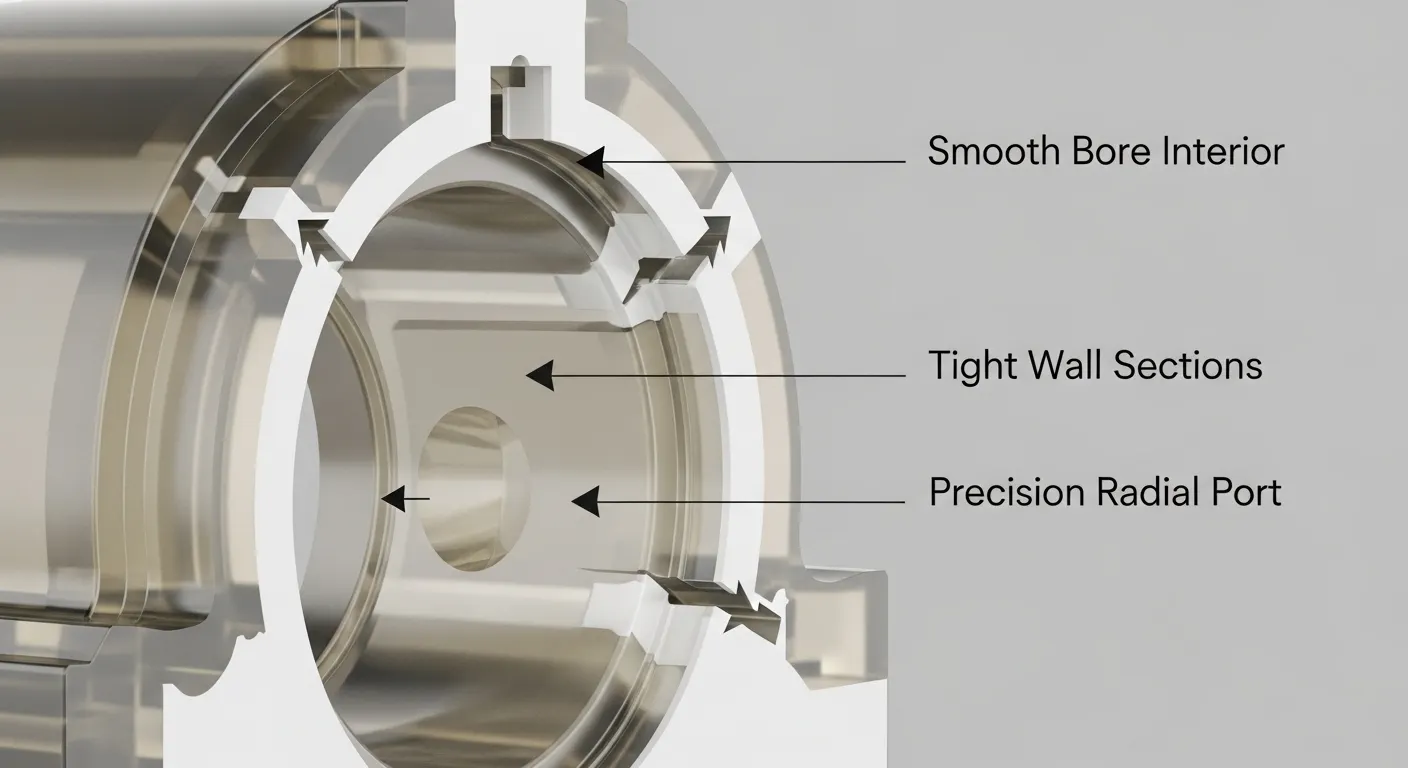
Project: Fluid valve housing for medical diagnostic equipment
Material: PEEK natural grade (ISO 10993-5 compliant)
Dimensions: 78 x 45 x 32 mm
Critical features: 38 mm deep blind bore, four radial fluid ports at 90°
Tolerance: ±0.02 mm on bore ID and port positions
Surface finish: Ra 0.8 µm on bore ID
Quantity: 20 units
Lead time: 7 working days
Machines: DMG Mori DMU 50 (5-axis finishing), Haas VF-2SS (roughing)
Result: All 20 units passed CMM inspection on first measure. Client ran 500 pressure cycles at 8 bar — zero failures. Product validation timeline cut by 3 weeks compared to their previous supplier.
See more examples in our CNC machining prototype case studies.
FAQ
What is the difference between a functional prototype and a visual prototype?
A visual prototype shows shape, size, and appearance. A functional prototype is built to the same engineering material specification as the final part and is tested under real operating conditions — pressure, load, temperature, chemical exposure. CNC machining produces functional prototypes; FDM 3D printing typically produces visual prototypes.
What is the minimum order quantity for CNC plastic prototypes?
There is no minimum order quantity for CNC plastic prototype machining. We regularly machine single units for design validation and first-article testing. Pricing per unit decreases as quantity increases from 1 to 50 units due to fixed setup amortization.
How accurate is CNC machining for plastic parts compared to metal?
For stable plastics like PEEK and Delrin, CNC machining achieves the same accuracy as aluminum: ±0.01 mm to ±0.02 mm on precision features. Softer or more hygroscopic plastics like Nylon require additional process controls (pre-drying, thermal stabilization) to achieve the same levels.
Can CNC machined plastic prototypes be used for regulatory submissions?
Yes. We provide full inspection certificates, material certifications (including biocompatibility, RoHS, and FDA compliance where applicable), and process documentation that supports ISO 13485 or AS9100 audit requirements. Contact us to discuss your specific documentation needs.
How does wall thickness affect the price of a plastic CNC prototype?
Walls below 1.5 mm typically require custom fixturing, slower feeds, and additional inspection points — all of which add cost. Designs with walls above 2.0 mm machine faster and cheaper. Our DFM review identifies these issues before quoting so you can make cost-driven design decisions before machining starts.
Conclusion
CNC machining services for plastic functional prototypes give engineering teams the fastest path from a CAD model to a part they can actually test. With tolerances down to ±0.01 mm, access to every major engineering plastic, and lead times of 3 to 7 working days, CNC machining removes the risk of committing to expensive tooling before your design is validated.
Whether you're building a single prototype for a fit check or 50 units for pre-clinical testing, the process works the same way: real material, real tolerances, real results.
Upload your STEP file at GD Prototyping and we'll return a DFM review and quote within 12 hours. No minimum quantity, no tooling cost, no delays.