
CNC Machining Low Volume Production: Aluminum Hydraulic Manifold for a European Fluid Control OEM
Project Summary
A European fluid control OEM needed 75 units of a precision aluminum hydraulic manifold for pre-series validation. GD Prototyping machined the parts from Aluminum 6061-T6 using full 5-axis milling on a DMG Mori NHX 5000, holding tolerances of ±0.02 mm on 14 intersecting port channels. All 75 units passed First Article Inspection. Parts were delivered in 12 business days, three days ahead of schedule.
Why CNC Machining Low Volume Production Is a Real Engineering Challenge
CNC machining low volume production sounds straightforward. In practice, it's one of the most technically demanding services a contract manufacturer can offer.
When a European fluid control OEM came to us needing 75 precision hydraulic manifolds, they had already been turned away by two suppliers. The reason: complex internal port geometry, an intersecting channel network with ±0.02 mm positional tolerance, and a 15-day delivery window. Their validation program was already running. They couldn't afford delays.
We took the project. Within 12 business days, we shipped 75 conforming parts. Here's exactly how we did it.
Project Overview
Our client designs and manufactures proportional hydraulic control systems for industrial automation equipment across Germany and the Netherlands. Their engineering team had finalized the manifold design and needed a pre-series run of 75 units to support system-level validation testing before committing to a higher-volume production order.
They chose GD Prototyping for three specific reasons:
- We offer full 5-axis milling with no minimum order quantities
- Our CNC machining case study portfolio showed directly comparable fluid control parts
- Our engineering team responded with a DFM review within 4 hours of receiving the STEP file
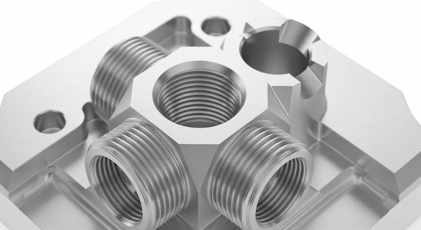
The manifold needed to handle 350-bar operating pressure, route hydraulic fluid across 14 intersecting internal channels, and mate with three separate valve sub-plates with zero-leak face seals. Every port bore had to be square to the mounting face within 0.02 mm.
Technical Requirements
| Parameter | Specification |
|---|---|
| Material Grade | Aluminum 6061-T6 |
| Part Dimensions | 187 mm × 142 mm × 96 mm |
| Critical Tolerance | ±0.02 mm (port centerline position) |
| General Tolerance | ±0.05 mm |
| Surface Finish (bores) | Ra 0.8 µm |
| Surface Finish (external) | Type II Anodize, Clear, 15–25 µm |
| Quantity | 75 units |
| Lead Time | 15 calendar days (delivered in 12) |
| Primary Process | Full 5-axis CNC milling |
| Secondary Process | CNC turning (threaded port inserts) |
| Thread Specifications | G1/4" BSPP and M10×1.5 metric ports |
Machining Approach and Process
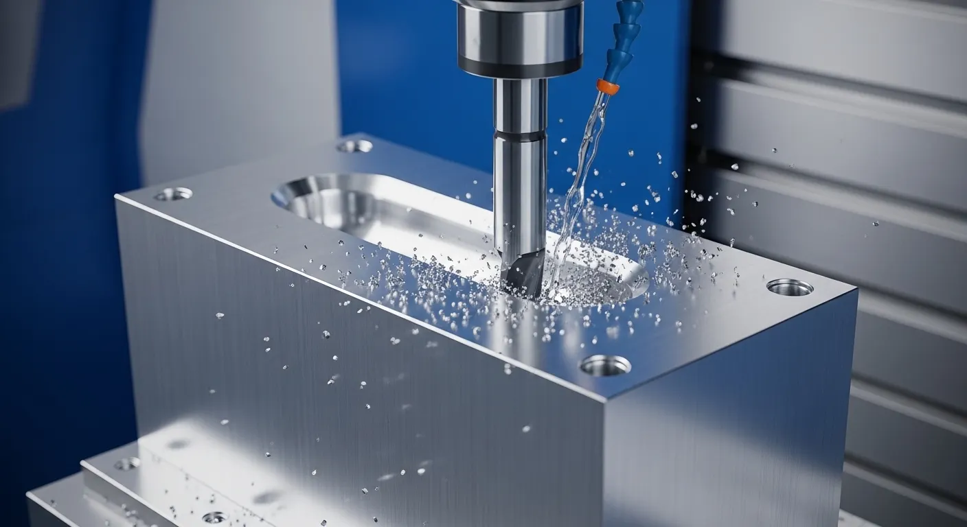
We machined all 75 manifolds from solid Aluminum 6061-T6 billet, starting from 200 mm × 150 mm × 100 mm rectangular stock. Our full process ran in six distinct stages.
Stage 1: CAM Programming and Toolpath Verification
Our CAM engineers built the toolpath in Mastercam 2025. The 14 intersecting internal bores required careful sequencing to avoid tool deflection at channel intersections. We ran virtual material removal simulation before cutting a single part.
Stage 2: Fixture Design and Workholding
We designed a dedicated fixture plate that clamped the billet from the bottom face. This gave us unobstructed 5-axis access to all five external faces in two setups. Setup 1 covered the top, front, back, and two side faces. Setup 2 flipped the part to finish the bottom mounting face and final port countersinks.
Stage 3: Roughing
We used the DMG Mori NHX 5000 5-axis machining center for all milling operations. Roughing used a 12 mm diameter 4-flute carbide end mill at 8,000 RPM, 3,500 mm/min feed. We left 0.4 mm stock for finishing on all critical bore walls.
Stage 4: Semi-Finishing and Finishing
Bore finishing used a 6 mm diameter 2-flute carbide reamer at 4,200 RPM. We achieved Ra 0.8 µm on all port bores in a single reaming pass. External faces were finish-milled with a 25 mm face mill to Ra 1.6 µm before anodizing.
Stage 5: CNC Turning (Threaded Ports)
Eight of the 14 ports required G1/4" BSPP threads and M10×1.5 metric threads. We ran these on our CNC turn-mill combo, cutting and threading in one operation to avoid re-chucking errors.
Stage 6: Surface Treatment
All 75 manifolds went through Type II clear anodizing to a 15–25 µm build. Anodize serves two functions here: it hardens the aluminum surface against fluid erosion at port entries, and it provides corrosion resistance for the external housing faces.
Challenges and Solutions
Challenge 1: Intersecting Bore Deflection at Deep Channel Crossings
Our first issue appeared during the programming phase. The 14-bore network had three locations where channels crossed at depths of 78 mm to 82 mm. At that depth, a standard 6 mm end mill generates tool deflection of 0.06–0.08 mm, which would push us outside tolerance before we even reached the reaming stage.
Our first attempt used a standard carbide end mill. The deflection showed up immediately in our virtual simulation, and we confirmed it physically on a test cut in an aluminum scrap block.
Solution: We switched to a solid carbide boring bar with a 6 mm shank and 90 mm reach, ground specifically for this application. We also reduced feed to 800 mm/min on the deep cross-bore segments and used a helical interpolation entry instead of a straight plunge. Deflection dropped to under 0.01 mm. Every subsequent bore came in at ±0.015 mm.
Challenge 2: Port-Face Perpendicularity After Anodizing
Type II anodizing builds 15–25 µm of oxide layer. That build-up is non-uniform on internal bore walls vs. external sealing faces. On our first three parts, the port bores were in-tolerance before anodizing, but after anodizing, the face seal surfaces measured 0.03 mm out of flat on one of the three valve mounting faces.
Solution: We introduced a post-anodize lapping step on the three critical valve mounting faces. Using a 400-grit lapping plate, we restored flatness to within 0.01 mm on all sealing surfaces. We updated the process sheet to include this step as standard for all hydraulic manifold projects requiring anodizing.
Challenge 3: Chip Evacuation in Blind Intersecting Bores
Blind intersecting bores trap aluminum chips. When chips re-enter the cutting zone, they scratch bore walls and push Ra beyond the 0.8 µm spec. We saw this on bore #7 and bore #11 during our pilot run on the first five parts.
Solution: We added high-pressure through-spindle coolant at 70 bar during all bore drilling and reaming passes. This cleared chips immediately on each peck cycle. Post-machining, each manifold went through a 20-minute ultrasonic cleaning bath in a deionized water and surfactant solution before CMM inspection. No further surface defects appeared across the remaining 70 units.
Quality Control and Inspection
We run ISO 9001-certified quality control on all low volume production orders. For this manifold project, our QC process covered four checkpoints.
In-Process Gauging: After each bore operation, our machinists checked bore diameter and depth with calibrated plug gauges and a depth micrometer. This caught the deflection issue on our test cuts before it reached production parts.
First Article Inspection (FAI): We completed a full FAI on parts 1, 5, and 10 before releasing the remaining 65 units for bulk machining. FAI measured all 47 critical dimensions on the STEP model, using our Zeiss Contura CMM with a 1 mm ruby probe stylus. Reported positional accuracy of the CMM: ±0.003 mm.
Dimensional Report: We delivered a full balloon drawing dimensional report for all 47 critical dimensions on each FAI part. The client's engineering team approved all three FAI reports within 24 hours.
Final Inspection: 100% of the 75 units received a visual and gauge inspection before packing. Pass rate: 75/75 (100%). Zero parts were rejected or reworked after the post-anodize lapping process was standardized.
Results and Outcome
We'll let the numbers speak.
- Delivery: 12 business days. Client's deadline was 15 calendar days. We shipped 3 days early.
- Inspection pass rate: 100% (75/75 units)
- Dimensional accuracy: All 47 critical dimensions within tolerance on every FAI part
- Surface finish: Ra 0.78 µm average across port bores (spec: Ra 0.8 µm)
- Client outcome: The client completed their hydraulic system validation tests without a single manifold-related leak or dimensional rejection
- Follow-on order: Two weeks after delivery, the client placed a 300-unit production order for the same manifold
The client's lead engineer noted that our DFM review identified a thread depth issue on port #3 before we started machining. That change alone would have taken 3 weeks to fix in the middle of a production run.
Why CNC Machining Was the Right Choice
For this application, CNC machining low volume production was the only realistic option. Here's why the alternatives didn't fit.
Die casting produces excellent surface finish but requires tooling that costs $8,000–$15,000 and takes 4–8 weeks to produce. For 75 units, tooling cost alone would have made unit pricing uncompetitive. Die casting also can't hold ±0.02 mm port-to-port positional accuracy without post-machining anyway.
3D printing (DMLS/metal SLM) can produce internal channels, but internal bore Ra of 0.8 µm requires extensive post-machining after printing. Lead time and per-unit cost for 75 printed aluminum parts would have exceeded CNC machining, not undercut it.
CNC machining required no tooling investment, started cutting in 48 hours from CAM sign-off, and delivered production-representative parts that the client could use directly in their validation system. Our CNC lathing service handled the threaded inserts in the same facility, keeping logistics simple.
For low-volume runs between 10 and 500 units where tolerances are tight and lead time is critical, CNC machining consistently outperforms both casting and additive manufacturing on total delivered cost and schedule.
FAQ: CNC Machining Low Volume Production
What is considered low volume in CNC machining production?
Low volume CNC machining typically covers runs of 1 to 500 units. It's ideal for pre-series validation, bridge production, and market-entry batches where investing in injection or die-cast tooling isn't justified. At GD Prototyping, we run low volume orders with no minimum quantity requirement.
How long does low volume CNC machining take to deliver?
Lead times vary by part complexity. Simple turned parts can ship in 3–5 business days. Complex 5-axis milled parts like hydraulic manifolds typically take 10–15 business days. Rush services are available. Our team responds with a DFM review and delivery estimate within 12 hours of receiving a STEP or IGES file.
What tolerances can CNC machining hold in low volume production?
Our 5-axis CNC centers hold positional tolerances of ±0.02 mm as standard on aluminum and steel parts. On very critical features, we can hold ±0.01 mm with dedicated fixturing and in-process gauging. Surface finishes down to Ra 0.2 µm are achievable with reaming and lapping.
What materials are available for low volume CNC machining?
We machine a broad range of metals including Aluminum 6061-T6, 7075, 2024, stainless steel 304 and 316, titanium alloys, and copper alloys. Engineering plastics such as PEEK, POM, Nylon, and PTFE are also available. We stock most materials in standard billet sizes for fast turnaround.
Is a First Article Inspection (FAI) available for low volume CNC orders?
Yes. We offer FAI with full dimensional reports on all low volume production orders. Inspections are performed on our Zeiss Contura CMM with results delivered in a balloon drawing format that matches your drawing revision. ISO 9001 documentation is available on request.
Get a Quote for Your Low Volume CNC Project
This hydraulic manifold project is a good example of what we do every week at GD Prototyping. Tight tolerances, complex geometry, short lead times, and no room for error.
If you're in pre-series validation, building a bridge production batch, or replacing a single failed component in an active product line, our team is ready to review your files today.
We'll send you a DFM review and delivery estimate within 12 hours. No commitment needed.
Browse our CNC machining case studies to see similar projects, or contact our team directly to start your quote.
We also offer CNC lathing for precision turned components, and our full rapid prototyping and low volume manufacturing services cover sheet metal, 3D printing, injection molding, and die casting if your project needs a different process.