


CNC Machining Aluminum Parts Before Anodizing: Dimensional Compensation Guide
CNC machining dimensions that pass inspection before anodizing may not remain within tolerance after surface finishing. Anodizing transforms a portion of the aluminum metal substrate into an anodic oxide layer, and causes part of the anodic layer to grow beyond the surface. The final layer thickness can be affected by pretreatment, etching, sealing, alloy composition, and coating thickness.
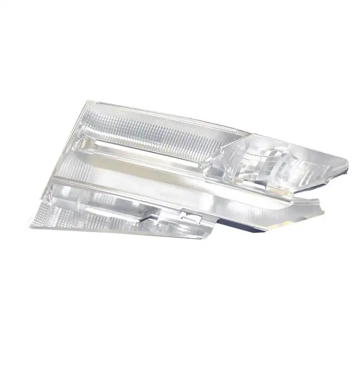
When it comes to the CNC Machining of Anodized Aluminum Parts, it is prudent to consider the allowances in advance of machining. Each feature should be considered separately, including but not limited to all openings, external diameters, threaded features, sealing grooves, and mating surfaces.
How Does Anodizing Change Aluminum Part Dimensions?
Anodizing is an electrochemical conversion process, not a conventional coating applied entirely above the surface. During treatment:
• Part of the aluminum substrate is converted into aluminum oxide.
• Part of the oxide layer remains within the original surface boundary.
• The remaining portion grows outward from the surface.
• Chemical etching or polishing may remove additional base material.
For conventional sulfuric acid anodizing, a commonly referenced rule of thumb is that approximately two-thirds of the oxide penetrates the substrate and one-third grows outward. This ratio should not be universally applied to all projects. Actual anodizing dimensional changes are influenced by alloy, process parameters, pretreatment, coating specification, and finishing supplier.
| Parameter | Meaning | Dimensional Effect |
| Total coating thickness | Complete anodic oxide thickness | Defines protection and finishing performance |
| Substrate consumption | Aluminum converted into oxide | Changes the original material boundary |
| Outward growth | Oxide extending above the original surface | Alters diameters, holes, slots, and clearances |
| Pretreatment removal | Material removed by etching or polishing | May offset part of the outward growth |
| Sealing influence | Final treatment of oxide pores | May affect measurement and functional surfaces |
A common mistake is assuming that the total coating thickness equals the total dimensional increase. Only the outward-growing portion directly increases an external surface or reduces an internal feature.
Which Features Require Compensation?
Not every surface on CNC Machining Aluminum Parts carries the same dimensional risk.
| Feature | Likely Change | Recommended Control |
| External diameter | Diameter increases | Machine slightly undersize |
| Internal hole | Effective diameter decreases | Machine oversize or mask |
| Narrow slot | Slot width decreases | Compensate both opposing walls |
| Internal thread | Thread clearance decreases | Mask, compensate, or tap afterward |
| Bearing bore | Fit may become too tight | Mask or finish-machine after anodizing |
| O-ring groove | Width and depth may change | Define final post-anodizing dimensions |
| Mating surface | Stack-up height changes | Apply tolerance compensation or masking |
| Sharp edge | Coating may become irregular | Add a practical chamfer or radius |
Precision fits should receive more attention than general cosmetic dimensions. H7 holes, dowel holes, bearing seats, sealing surfaces, and sliding interfaces often require masking or post-anodizing machining.
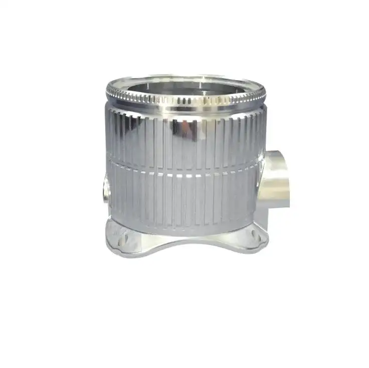
Calculating Pre-Anodizing Dimensions
For an external feature anodized on two opposite surfaces:
Final external size ≈ Pre-anodizing size + 2 × outward growth
For an internal hole:
Final hole size ≈ Pre-anodizing hole size − 2 × outward growth
These formulas explain the compensation direction, but they should not be treated as universal production values. The actual outward growth must be confirmed against the specified anodizing process.
For example, a precision shaft may be machined slightly below its final target so the oxide growth brings it into tolerance. A locating hole may be machined larger before anodizing because oxide forms around the full circumference and reduces the usable diameter.
To enhance the quality of high-precision CNC machining of aluminum components, the following steps can be taken:
- State the final dimension required after anodizing.
- Determine expected coating thickness and outward growth.
- Account for material removal during pretreatment.
- Manufacture a first article.
- Conduct measurement of the component pre and post finishing.
- Use verified data to modify the machining offset.
Hard Anodizing vs. Conventional Anodizing
For applications in need of surface customization in terms of color as well as in demand of corrosion resistance, anodizing is most often preferred. For wear resistant applications, hard anodizing is preferred.
| Consideration | Conventional Anodizing | Hard Anodizing |
| Typical purpose | Decorative and protective | Functional and wear-resistant |
| Dimensional effect | Usually moderate | Usually more significant |
| Critical features | Fits and cosmetic surfaces | Holes, threads, bores, and sliding surfaces |
| Common control | Machining allowance or local masking | Masking, larger allowance, grinding, or post-machining |
| Validation | Thickness and dimensional checks | First article, gauges, thickness, and functional testing |
The anodizing type alone does not determine the correct allowance. Compensation must be based on the actual coating requirement and feature tolerance.
How Pretreatment Affects Final Results
Surface preparation can influence both dimensions and appearance. Alkaline etching may remove a small amount of aluminum and increase roughness. Chemical or mechanical polishing changes the surface profile, while blasting produces a matte finish and can soften sharp edges.
Anodizing will not hide deep tool marks, scratches, fixture impressions, or inconsistent surface texture. In many cases, it makes these defects more visible.
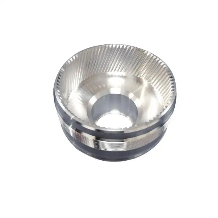
Before anodizing, manufacturers should control:
• Tool sharpness and spindle runout
• Finishing step-over and feed marks
• Burrs around holes and edges
• Fixture pressure marks
• Handling scratches
• Surface roughness consistency
• Chamfer and radius geometry
Cosmetic, functional, conductive, sealing, and masking surfaces should be identified separately on the drawing.
Material Selection: 6061 vs. 7075
6061 aluminum is the more typical substrate for housings, brackets, frames, and general engineering components due to excellent machinability and a relatively consistent anodized appearance.
Due to its strength, 7075 aluminum is used more often in aerospace, robotics, and structural components with heavy loads. 7075 can have more pigment variation than 6061. Because of this, it is the responsibility of the manufacturer to confirm that the appearance of 7075 aluminum, before production, matches an approved sample.
When creating drawings for anodized CNC Machining Aluminum Parts, you must list the following:
• Aluminum alloy and temper
• Anodizing specifications
• Coating thickness
• Color and gloss
• Surface prep
• Sealing
• Masked areas
• Rack marks
• Inspection condition
Reference to ISO 7599 can help with explaining what is required for decorative and protective anodizing as it pertains to standards, performance, and testing and inspection.
Threads, Fits, and Masking
There are three common practices to deal with threads during the coating process.
• Masking – maintains threads and allows for electrical continuity to be preserved.
• Compensation – alters the threads to accommodate the expected coating thickness.
• Machining – allows threads to be cut to final dimensions, but local protection oxidation is removed.
Masking is often used on the aforementioned features. However, the practice of masking introduces visible artifacts and a lack of corrosion protection, so the placement of masking should be done during the design and manufacturing process.
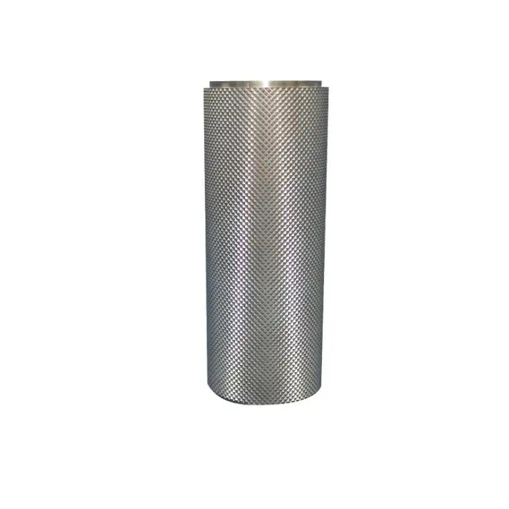
Inspection Following Anodizing
Both finishing quality and functional dimensions should be verified through inspection. The first article inspection report typically defines the following:
• Pre-Anodizing dimensions
• Post-Anodizing critical dimensions
• Coating thickness
• Dimensions of holes and bores
• Results of the thread plug or ring gauge
• Surface finish
• Flatness
• Appearance uniform
• Color consistency
• Fit for assembly
For production batch orders, recording the shift in dimensions before and after anodizing creates a reliable database for compensation.
How GD Prototyping Adds Value to Anodized Aluminum Components
When close tolerances, specific coating thickness, or cosmetic surface requirements are essential, it is advantageous to have machining and anodizing treated as a single, unified process.
GD Prototyping is focused on the CNC machining of aluminum parts within the 6061, 7075 series and other engineering aluminum grades. Our focused workflows will address both the prototyping and production side of machining, surface finish requirements, masking, compensation, anodizing, and post-finish inspection.
With this approach, it is possible to provide an integrated answer to surface finish, and corrosion and wear protection as well as color, and dimension stability for the automotive, aerospace, electronics, medical, and consumer industries.
Final Recommendations
Successful CNC Machining Aluminum Parts should be designed around the final anodized condition, not only the machined condition. Compensation must account for outward oxide growth, substrate conversion, pretreatment removal, alloy behavior, and final tolerance.
Precision holes, threads, sealing grooves, and mating features should each receive a specific strategy involving compensation, masking, or post-anodizing machining.
Planning anodized aluminum components with demanding dimensional or appearance requirements? GD Prototyping will evaluate your drawings along with the selection of alloys and coatings, and assess masking areas and inspection criteria before production. This evaluation will minimize rework related to the development of prototypes and their subsequent manufacture.
FAQs
Q1. Which aluminum grades does GD Prototyping apply when CNC machining aluminum parts?
Typical grades include 6061, 6063, 5083 and 7075 aluminum. GD Prototyping selects these and other alloys based on strength and corrosion resistance, as well as ease of machining, final part appearance after anodizing, and other factors.
Q2. Can GD Prototyping adjust dimensions if anodizing is to be done?
Definitely. GD Prototyping considers coating thickness, growth of the oxide layer, critical tolerances, the areas to be masked and requirements for final assembly before machining. Appropriate allowances for features and tolerances are applied.
Q3. Does GD Prototyping examine parts after anodizing?
Definitely. GD Prototyping performs final inspection of anodized parts to check the functionality of threads, appearance and consistency of color, flatness and surface finish, and coating thickness, as well as critical dimensions and assembly requirements.
Q4. Can GD Prototyping preserve precision holes and threads during anodizing?
Definitely. GD Prototyping provides the ability to mask precision holes (including dowel, bearing, and seal surfaces), threaded holes, and electrical contacts. For precision requirements beyond what anodizing allows, GD Prototyping offers post-anodizing machining.
Q5. Does GD Prototyping offer CNC machining and anodizing support?
Definitely. GD Prototyping offers an integrated service for CNC machining, dimensional compensation, surface preparation, anodizing, masking, and final inspection, thus eliminating the problems associated with multiple suppliers.
