


CNC Machining Aluminum Guide: Common Defects and Root Cause Analysis
Aluminum is preferred in more applications within CNC machining than other alloys due to its lightweight and excellent thermal conductivity paired with high corrosion resistance, and, most importantly, ease of cutting when compared to steel and titanium. However, due to its ease of cutting (removing material), it can lead to problems in machining like dimensional instabilities and the presence of uneven surfaces.
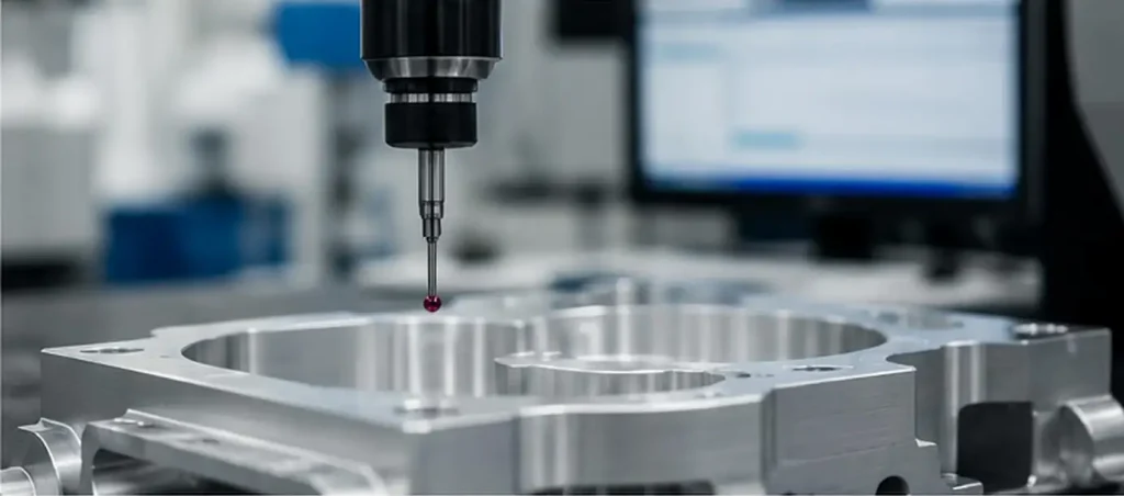
Aluminum can stick to the cutting tool edges, expand and, thus, deform during machining (clamping) due to thermal effects, and cause further issues by relaxing internally (becoming stress-free) after the material is significantly removed. This machining guide explains how to classify the most common machining defects of aluminum, identify their causes, and eliminate them, thus reducing the iterative/trial and error process.
How to Classify Aluminum CNC Machining Defects?
Aluminum machining defects can be classified into four categories:
• Dimensional defects: Lead to oversized holes, positioning errors, loss of flatness, and variation from one batch to another.
• Surface defects: Presence of tool marks, surface chatter, tearing, scratching, and dents, and inconsistent surface roughness.
• Edge and feature defects: Presence of burrs, rolled edges, damage to thin features, incomplete threads, and poor quality in deep hole machining.
• Structural defects: Thin-wall deformation, warping, residual-stress movement, and dimensional changes after anodizing.
Classifying the visible symptom first narrows the investigation to the material, cutting tool, parameters, fixture, machine condition, thermal behavior, coolant, or handling method.
Common Aluminum Machining Defects and Root Causes
| Defect | Likely root causes | First inspection point | Typical corrective action |
| Built-up edge | Heat, friction, poor evacuation | Cutting edge and coolant direction | Use a sharper tool and improve chip removal |
| Burrs | Worn tool, unsupported exit edge | Tool condition and toolpath | Change cutting direction or add chamfers |
| Chatter marks | Low rigidity, unstable parameters | Tool overhang, fixture, spindle speed | Reduce overhang and cutting load |
| Dimensional drift | Heat, wear, datum movement | Temperature and production trend | Stabilize temperature and apply controlled compensation |
| Thin-wall distortion | Clamping force, residual stress | Free-state dimensions | Reduce clamping force and machine in stages |
| Scratches | Chip recutting or handling | Scratch direction and location | Improve flushing and part protection |
| Hole-size error | Runout, tool wear, poor evacuation | Runout and hole sequence | Add a controlled finishing operation |
| Thread damage | Incorrect pilot hole or trapped chips | Pilot-hole size and thread form | Optimize hole preparation and tapping cycle |
Built-Up Edge and Chip Welding
Built-up edge occurs when aluminum adheres to the cutting edge and changes the tool's effective geometry. The accumulated material can break away intermittently, leaving a torn surface or causing dimensional variation.
Common Causes Include:
• An improper or dull cutting edge.
• Insufficient flute space.
• Excessive heat in the cutting zone.
• Low feed per tooth resulting in rubbing instead of cutting.
• Poorly directed coolant.
• Chips left in pockets.
Since increasing spindle speed alone is a partial solution, increasing spindle speed without increasing feed or evacuation can lead to even higher levels of friction. Regarding milling aluminum, the optimal solution is directing coolant or compressed air to the cutting zone while maintaining sufficiently thick chips, low runout, and using aluminum-specific cutting tools.
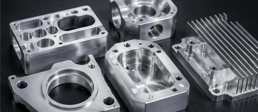
Burrs and Rolled Edges
Due to aluminum's high ductility, edge burrs grow as plastic deformation occurs at unsupported or poorly designed edges. Since tool withdrawal causes deformation of the workpiece, exit burrs grow larger than entry burrs.
While burr removal is commonly associated with post-machining deburring, controlling burrs is most effective at the design level of tool paths by employing one or more of the following:
• Design edge chamfers.
• Contour finishing with the allowance of stock.
• Preventing tool exit through unsupported edges.
• Minimal time between machining operations to ensure the edges remain supported.
The presence of burrs may also be caused by excessive tool wear, poor edge support, excessive runout, or poor machining conditions.
Tool Marks, Chatter, and Surface Scratches
While all of these defects may appear to be similar, there are a number of different causes.
Wavy or irregular lines on the surface are more indicative of chatter while regular lines are more indicative of tool path programming and the machining feed. The presence of scratches on the surface of the workpiece is more indicative of poor chip evacuation and handling of the workpiece.
A new cutter does not ensure a good finish. Surface problems may still result from:
• Contamination between the tool and holder
• Excessive cutter extension
• Collet or spindle runout
• Uneven finishing allowance
• Poor chip evacuation
• Parameters that do not match the actual tool diameter and flute count
To address chatter in your setup, first examine the tool and holder, and reduce overhang. Next, improve support for the workpiece and adjust the spindle speed, axial depth, and radial engagement. Since multiple factors can be addressed at the same time, the root cause can be difficult to determine.
Thermal Effects and Dimensional Drift
When machining aluminum, you may think you've captured the dimensions accurately, but the workpiece may actually be out-of-tolerance once the part is measured after it cools. Thermal effects may be present during the manufacturing process on the workpiece, spindle, cutter, and fixture.
Drift can also be caused by factors such as tool wear and machine warm-up, as well as unstable datum and the release of residual stress during the roughing cycle. It can be helpful to take measurements of the first, middle, and last parts of a production batch. If there is a gradual shift in one direction, it is most often the result of wear, thermal effects, or a compensation error.
Dimensional stability can be improved by:
• Separating roughing and finishing
• Leaving uniform finishing allowance
• Allowing stressed parts to stabilize
• Using repeatable datums
• Controlling inspection temperature
• Recording tool life and offset changes
Thin-Wall Deformation
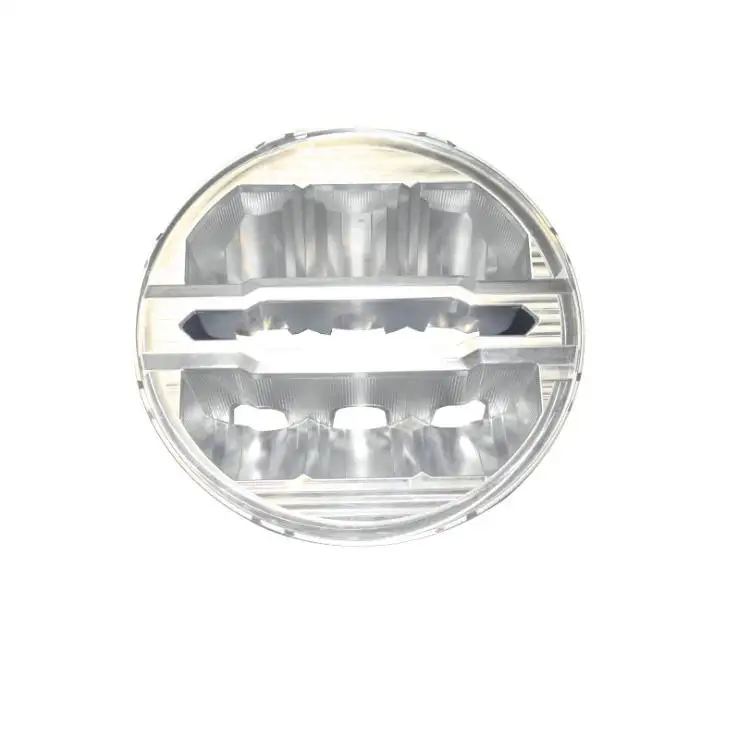
Thin walls may appear accurate while clamped but move after the fixture is released. Excessive clamping force can temporarily push the component into the required shape. Once unclamped, elastic recovery causes flatness, profile, or hole-position errors.
A practical machining sequence is:
Symmetrical roughing → uniform stock allowance → intermediate stabilization → low-force reclamping → layered finishing → free-state inspection
Design changes may also be necessary. Larger transition radii, more uniform wall thickness, temporary support features, and improved datum locations can reduce deformation more effectively than parameter changes alone.
Preventing Defects Before Production
A useful CNC Machining Aluminum Guide should begin before the first toolpath is programmed. The drawing review should identify critical fits, sealing surfaces, cosmetic areas, anodized features, thin walls, deep cavities, and incomplete geometric-tolerance references.
The grade of aluminum needs to be identified for the application. If good machinability and corrosion resistance are the most important characteristics, then selecting Aluminum 6061 would be appropriate. Aluminum 7075 would be a stronger choice, but would need more control in the processes. Aluminum 2024 would be a good choice for strength and fatigue. Aluminum 5052 and 6082 exhibit different characteristics based on their temper and alloying composition.
The RFQ must define the inspections to be performed including critical dimensions and surfaces, datums, surface roughness, and anodizing allowances. It must also state the acceptance criteria and report requirements.
Practical Strategies to Control Risks of Machining Aluminum
The combination of early engineering reviews, the appropriate level of control on the processes, the design of the fixturing, and integrated inspection and finishing processes reflect the risk mitigation strategy for machining aluminum that GD Prototyping employs.
| Risk Area | Control Strategy | Practical Benefit |
| Datum and Setup Errors | Select appropriate axis milling or CNC turning based on part geometry | Eliminates the need for repeated clamping and improves positional accuracy. |
| Tool Deflection | Select tool angles with minimum overhang | Reduces tool chatter and dimensional errors and improves surface consistency. |
| Thin-Wall Deformation | Consider wall thickness, machining sequence, fixture support, and clamping considerations | Minimizes distortion of thin walls after removal from the fixture. |
| Variation in Tolerances | Consider principal features and dimensions based on geometric and feature access consideration of reasonable limits on tolerances | Access consideration of reasonable limits on tolerances |
| Surface Defects | Optimize the cutting sequence and tooling based on the requirement of inspection and with established finish allowance | Removes critiques on finish |
| Post Processing Changes | From the available alternatives of anodizing, polishing, sandblasting, surface brushed finish or leaving the part as machined in the production run | Protects dimensions and finishes of the part |
| Delay in Communication | Provide direct support to the project with the aim of product response to instructions within 12 hours of posting drawings and decisions being clarified and corrected | Posting drawings and decisions being clarified and corrected |
Surface roughness to Ra 0.2 μm and tolerances of ±0.05 mm are achievable depending on the part size, material, geometry, and type of finishing.
Closing Thoughts
The best strategy for controlling defects involves a combination of material selection, tool design, stable fixturing, appropriate cutting, chip removal, thermal control, and planned inspection. Adjusting a single factor usually does not address the combination of issues presenting simultaneously.
For aluminum components affected by burrs, chatter, dimensional drift, thin-wall deformation, or poor surface finish, GD Prototyping can assess your drawing, alloy selection, tolerances, finishing, and quantity of your order. Please send project information for a quick assessment of manufacturability and an aluminum machining process plan.
FAQs
Q1. What aluminum CNC machining services does GD Prototyping provide?
In addition to their CNC Turning service, GD Prototyping offers 3-, 4-, and 5-axis and 3+2 CNC Milling services. These allow for the machining of not only simple components, but also parts with multiple sides, deep cavities, complex surfaces, and rotating features.
Q2. Which aluminum alloys can GD Prototyping machine?
GD Prototyping provides machining for many structural and high strength aluminum alloys such as 6061, 7075, 5052, 2024, 5083, and 6082. While each of these alloys has unique characteristics, the final selection should consider machining, surface treatments, and the requirements for the strength and corrosion resistance of the components.
Q3. How does GD Prototyping reduce setup-related machining errors?
Using multi-axis machining reduces the number of setups required to machine parts/surfaces with multiple features, which helps to eliminate errors due to variations in clamping, excessive tool extension, and errors in the positioning of related features.
Q4. Can GD Prototyping machine thin-wall aluminum parts?
Yes. Thin-wall aluminum machining projects can be evaluated for wall thickness, machining sequences, fixture and clamp supports, residual stresses, and finishing allowances. Due to the nature of thin-wall components, a range of achievable tolerances will be defined based on design and feature accessibility.
Q5. What tolerances can GD Prototyping achieve?
While published tolerances are generally as low as ±0.05 mm, this value should be considered a guideline. Achievable tolerances should be defined based on part and feature geometry, wall thickness, aluminum grade, and surface finish.
