


CNC Machining Services for Aluminum Enclosure: A Case Study
We machined 150 aluminum enclosures from 6061-T6 billet for a German industrial automation OEM. The enclosures measured 180 x 120 x 45 mm with ±0.02 mm tolerances and a Type II anodized finish. We delivered all 150 units in 12 working days with a 99.3% first-article pass rate. Here's exactly how we did it.
Introduction
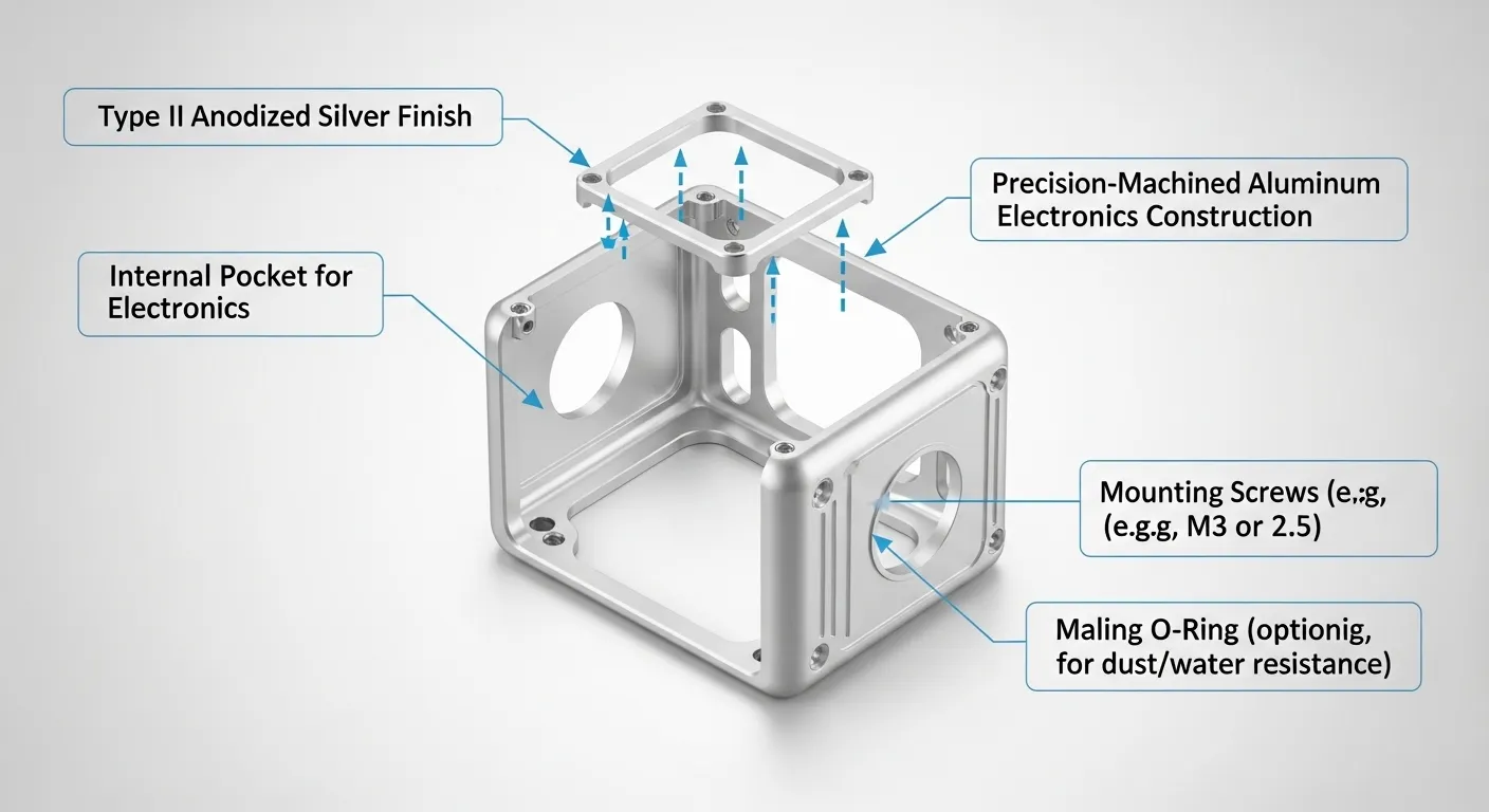
The client sent us a DXF file and a tight deadline. Their previous supplier had scrapped 18% of a batch due to thin-wall deformation on the side panels. They needed a reliable CNC machining partner who could hold ±0.02 mm on a part with 1.2 mm walls and deliver in under two weeks.
We'd machined aluminum enclosures for industrial clients before, but this project had three real challenges stacked on top of each other: thin walls, deep internal pockets, and an anodizing requirement that punished any surface deviation above Ra 1.6 μm. This case study walks through exactly what we did, what failed first, and how we fixed it.
Project Overview
The client was a mid-sized industrial automation manufacturer based in Stuttgart, Germany. They needed precision aluminum enclosures to house proprietary motor control PCBs used in conveyor automation systems. The enclosures needed EMI shielding integrity, tight lid-to-body fit, and a hard anodized exterior for chemical resistance in factory environments.
Key project requirements:
- 150 units in a single production run
- CNC-machined from billet (no casting allowed per engineering spec)
- Internal pocket depth of 38 mm with four M3 thread bosses
- Lid mating surface flatness within 0.025 mm
- Type II anodize, clear, per MIL-A-8625F
Technical Specifications
| Parameter | Details |
|---|---|
| Material | Aluminum 6061-T6 |
| Part Dimensions | 180 x 120 x 45 mm (body); 180 x 120 x 6 mm (lid) |
| Wall Thickness | 1.2 mm (minimum) |
| Tolerance | ±0.02 mm on critical features; ±0.05 mm general |
| Surface Finish | Ra 1.6 μm pre-anodize; Type II clear anodize post-process |
| Thread Spec | M3 x 0.5, 6H tolerance |
| Quantity | 150 enclosure bodies + 150 lids = 300 total parts |
| Lead Time | 12 working days |
| Primary Process | 5-axis CNC milling |
| Secondary Process | CNC turning (lid locating bosses), deburring, anodizing |
| Machine | DMG Mori DMU 50 (5-axis), Haas VF-2 (3-axis roughing) |
Machining Process
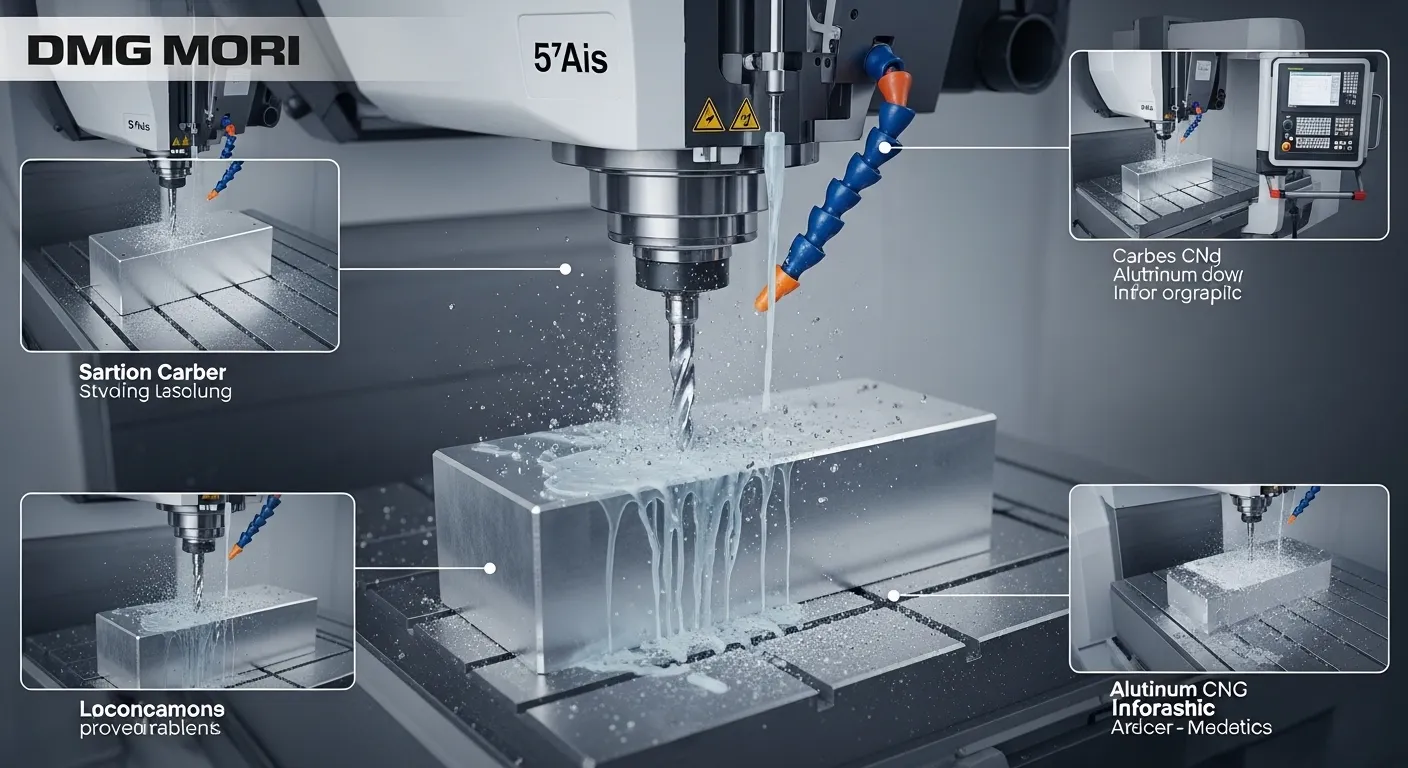
We split the job into three phases: roughing, semi-finishing, and finishing. Each phase had its own fixturing setup.
Phase 1: CAM Programming and Setup
Our CAM engineer ran the part in Mastercam, using adaptive clearing toolpaths for roughing. We targeted 70% stock removal on the Haas VF-2 before moving parts to the DMG Mori for finishing. This split reduced DMG Mori cycle time from 38 minutes to 22 minutes per part.
Roughing parameters on the Haas VF-2:
- 12 mm 3-flute carbide end mill
- Spindle speed: 12,000 RPM
- Feed rate: 3,200 mm/min
- Depth of cut: 3 mm
- Flood coolant on throughout
Phase 2: 5-Axis Finishing
We moved roughed parts to the DMG Mori DMU 50 for all critical features. The 5-axis setup let us machine the internal pocket, lid mating face, and M3 boss features in a single clamping operation. This eliminated re-fixturing error, which was the root cause of the previous supplier's tolerance failures.
Finishing parameters:
- 6 mm 2-flute polished carbide end mill (ZrN coated)
- Spindle speed: 18,000 RPM
- Feed rate: 1,800 mm/min
- Axial depth: 0.3 mm per pass
Phase 3: Threading and Deburring
M3 threads were cut with a forming tap at 300 RPM with neat cutting oil. All parts went through a vibratory deburring cycle (45 minutes) before inspection. We sent confirmed parts to our anodizing partner within 24 hours of sign-off.
Challenges and Solutions
This section is the most important part of the case study. Two problems cost us half a day of production time early in the run.
Challenge 1: Thin-Wall Deformation During Roughing
On the first 10-part trial batch, we saw 0.08 mm outward bow on both 1.2 mm side walls after roughing. The Haas VF-2 was applying too much radial cutting force during the aggressive adaptive clearing passes.
First attempt: We reduced feed rate by 20%. The bowing improved but didn't go away. At 0.045 mm, we were still outside spec.
Fix that worked: We changed the fixturing strategy. Instead of clamping the part at both ends of the long axis, we added a central support fixture made from nylon. This distributed clamping pressure and reduced free-span wall vibration. We also switched from adaptive clearing on the walls to a dedicated wall-finishing pass at 0.5 mm radial depth of cut. Bowing dropped to 0.007 mm, which is well within the ±0.02 mm spec.
Challenge 2: Lid Mating Surface Flatness
The client spec required lid-to-body flatness within 0.025 mm over the 180 mm face length. Our first batch measurement showed 0.038 mm deviation, caused by thermal growth in the aluminum after heavy roughing.
Fix: We introduced a 15-minute cooldown rest after roughing before finishing the mating face. We also reduced spindle speed for the facing pass from 15,000 to 11,000 RPM to cut heat input. Final flatness across the full production run averaged 0.016 mm, well inside spec.
Quality Control
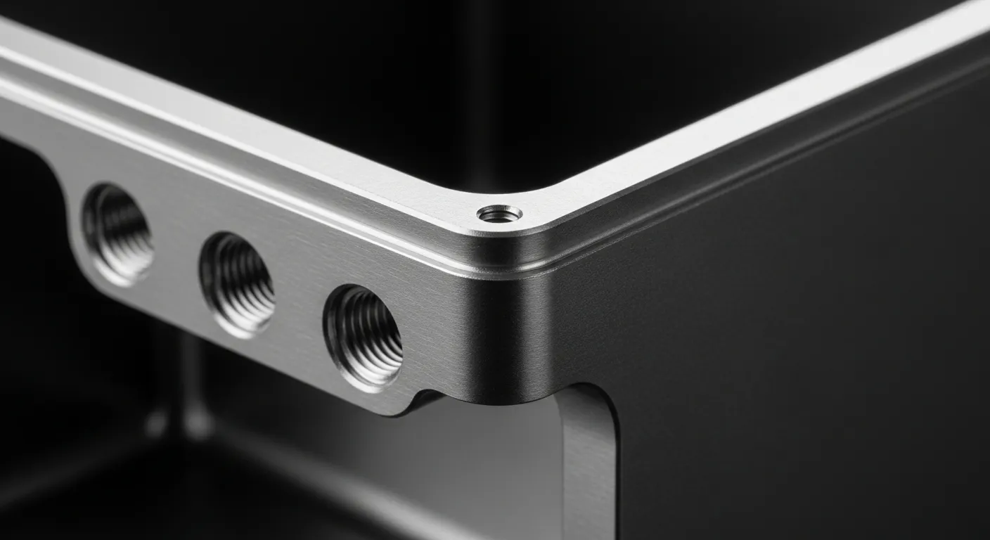
We used a Zeiss Contura CMM for all first-article inspections. Every first article report (FAR) covered 22 critical dimensions, including:
- Pocket depth: 38.00 mm ± 0.02 mm
- Lid mating face flatness: 0.025 mm max
- M3 thread go/no-go gauge per DIN EN ISO 1502
- Wall thickness at six points per part
- Overall body length, width, height
For production parts, we inspected every 15th part using a statistical sampling plan (AQL 1.0, Level II per ANSI/ASQ Z1.4). Any batch measurement outside control limits triggered a 100% check of the preceding 15 parts.
Surface roughness was verified with a Mitutoyo SJ-210 profilometer. Pre-anodize Ra averaged 1.3 μm, which gave the anodizing process a clean surface to work with and produced a consistent, even coating.
All CNC machining prototype cases we work on follow this same CMM-backed inspection process.
Results
The numbers mattered here. Here's what we delivered:
- Delivery: 150 complete enclosures (body + lid) in 12 working days
- First-article pass rate: 99.3% (149/150 units passed CMM inspection without rework)
- 1 unit reworked: One lid had a flatness deviation of 0.031 mm, caught at inspection, re-faced in 8 minutes, and re-inspected before shipping
- Scrap rate: 0% (zero parts scrapped vs. 18% at the client's previous supplier)
- Post-anodize dimensional change: Average 0.008 mm growth per face, fully within client tolerance
- Client feedback: EMI gasket seating fit confirmed on all 150 assemblies; no field failures reported after 3 months of production use
This outcome was possible because we combined 5-axis fixturing discipline with real-time in-process checks at every phase. Our CNC machining services are designed to handle exactly this kind of tight-tolerance, multi-feature aluminum work.
Why CNC Machining Was the Right Choice
The client's engineering team had considered two alternatives: die casting and DMLS metal 3D printing.
Die casting was ruled out at 150 units. Tooling cost for an aluminum die casting mold starts at $8,000-$15,000 and takes 4-6 weeks to cut. That's not viable for this volume or timeline.
DMLS 3D printing could have made the geometry, but surface finish on as-printed aluminum requires significant post-processing to reach Ra 1.6 μm, and dimensional accuracy on internal thread bosses in DMLS rarely meets 6H tolerance without secondary machining anyway.
CNC machining from billet gave us:
- Full 6061-T6 material properties (no porosity, no grain variation from casting)
- Direct tolerance control without secondary operations
- Anodizing-ready surface in a single setup
- No tooling cost at 150 units
For volumes between 10 and 500 units, CNC machined aluminum enclosures consistently beat both alternatives on cost, lead time, and dimensional reliability. You can also explore our sheet metal fabrication and die casting services if your volume or geometry requires a different approach.
FAQ
What aluminum grade is best for machined enclosures?
6061-T6 is the most common choice. It machines cleanly, anodizes well, and offers a good strength-to-weight ratio. For higher strength applications, 7075-T6 works better but costs more and is slightly harder to anodize evenly. We use 6061-T6 for over 80% of our aluminum enclosure projects.
What tolerance can you hold on aluminum enclosures?
We routinely hold ±0.02 mm on critical features like mating faces and bore diameters using 5-axis CNC milling. General profile tolerances run ±0.05 mm. For features tighter than ±0.01 mm, we use dedicated CMM-guided finishing passes.
What's the minimum wall thickness we can machine?
We've successfully machined walls as thin as 0.8 mm in 6061-T6 using low-force finishing passes and custom support fixtures. Walls under 1.0 mm require careful fixturing and reduced cutting forces to prevent deformation.
How does anodizing affect final dimensions?
Type II anodizing (clear, 5-25 μm thickness) adds roughly 0.005-0.015 mm per face. We account for this in the machining program by leaving the anodize stock allowance on critical surfaces. For hard anodize (Type III), growth can reach 0.025-0.050 mm and must be planned into the design.
Can you handle NDA-protected designs?
Yes. GD Prototyping operates under strict confidentiality agreements. We don't share drawings, part files, or client details without written consent. This is especially important for clients in pre-production stages. You can request a confidential quote here.
Conclusion
Aluminum enclosure machining looks straightforward until you're holding a 1.2 mm wall to ±0.02 mm over a 180 mm span. Getting it right requires the right fixturing strategy, proper thermal management between operations, and CMM-backed inspection at every stage.
We machined 150 units in 12 days with a 99.3% pass rate and zero scrap. If you have a similar aluminum enclosure project, whether it's a prototype run of 5 or a batch of 500, send us your drawings for a free quote. Our team responds within 12 hours.
Explore our CNC machining case studies to see more precision aluminum projects like this one.
