
CMM Inspection Report Checklist: A Complete Guide
In the world of precision manufacturing, a part is not correct until it is proven to be correct. A visual check or a simple measurement with calipers is not enough for complex components. For critical parts, quality must be verified with objective, traceable, and highly accurate data. The gold standard for providing this proof is the Coordinate Measuring Machine (CMM) inspection report. This document is the final verdict on a part's quality. It is the essential link between the digital design and the physical product.
A CMM inspection report is a formal document that provides detailed, high-precision measurement data for a manufactured part. It compares the actual measured dimensions of the part against the nominal dimensions and tolerances specified in the 3D CAD model and 2D engineering drawing. Understanding how to read and interpret this report is an essential skill for any engineer, designer, or quality manager.
As a manufacturer of high-precision components, GD-Prototyping provides comprehensive CMM inspection reports as a standard part of our quality assurance process. This guide is designed to demystify these reports. We will break down the anatomy of a report, explain what each section means, and provide a detailed checklist for a proper review.
What is a CMM and Why is its Report the Gold Standard?
To understand the report, one must first appreciate the technology that generates it. A Coordinate Measuring Machine is a sophisticated and highly accurate piece of metrology equipment.
The Role of the Coordinate Measuring Machine (CMM)
A CMM is a device that measures the geometry of a physical object with incredible precision. It operates in a three-dimensional Cartesian coordinate system (X, Y, Z). The machine uses a very sensitive probe to touch discrete points on the surface of the part. By recording the X, Y, and Z coordinates of each of these points, it can construct a digital representation of the part's geometry. This data is then used to calculate a wide range of measurements. This includes distances, diameters, angles, and complex geometric tolerances.
Why CMM Reports Are Essential
CMM reports are the industry standard for part verification for several key reasons.
- Objective Proof of Quality: A CMM report replaces subjective assessment with hard, quantifiable data. The measurements are traceable to international standards, providing an unbiased and authoritative record of the part's condition.
- Ability to Measure Complex Geometry: Calipers and micrometers are limited to simple measurements. A CMM is the only practical way to accurately measure complex, contoured surfaces. It is also essential for verifying Geometric Dimensioning and Tolerancing (GD&T) callouts, such as flatness, position, and profile.
- Traceability and Process Control: The report provides a permanent, documented record of a part's quality. This is crucial for industries that require traceability, such as aerospace and medical. The data can also be used for Statistical Process Control (SPC) to monitor the health and consistency of a manufacturing process over time.
The Anatomy of a CMM Inspection Report
A comprehensive CMM report is a dense document packed with information. While the format can vary slightly between different software platforms, all professional reports will contain the same core sections. Understanding the purpose of each section is key to a proper review.
Breaking Down the Key Sections of the Report
The Header Section: General Information
This is the top section of the report. It provides the high-level administrative details needed to identify the part and the inspection event. It should always include:
- Part Name and Part Number: To identify the component.
- Part Revision Level: To ensure the part was inspected against the correct version of the drawing.
- Serial or Lot Number: To identify the specific part or batch being inspected.
- Date and Time of Inspection: For traceability.
- Inspector's Name: To identify the responsible personnel.
- Drawing and CMM Program Names: To link the report to the source documents.
Part Setup and Alignment Information
This is a critical, and often overlooked, section. It explains how the part was physically located in the CMM's 3D coordinate system. A part must be properly "aligned" for its measurements to be meaningful. This section will detail the specific datum features from the engineering drawing that were used to establish the part's origin and orientation. A common alignment might be a "Plane, Line, Point" sequence. An incorrect alignment is a common source of a failed report.
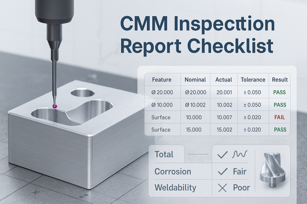
The Feature Measurement Data
This is the main body of the report. It contains a line-by-line list of all the individual features that were measured. Each line provides a complete set of data for a single measurement.
- Feature ID: A clear name for the feature being measured (e.g., "Hole_1," "Plane_A," "Slot_Width").
- Nominal: The target value for the dimension as specified in the CAD model or on the drawing.
- Actual: The actual value of the dimension as measured by the CMM.
- Deviation: The mathematical difference between the Actual and the Nominal values (Deviation = Actual - Nominal).
- Tolerance: The total acceptable range of variation for the dimension as specified on the drawing (e.g., ±0.1 mm).
- Out-of-Tolerance (OUTTOL): The amount by which the Deviation exceeds the allowable Tolerance. This column should be zero for a passing feature. It will be clearly flagged, often in red, for any failing feature.
Geometric Dimensioning and Tolerancing (GD&T) Results
This section is dedicated to the verification of complex GD&T callouts from the drawing. While the previous section measures simple sizes, this section measures form, orientation, and location. It will report the results for tolerances such as:
- Flatness and Straightness
- Perpendicularity and Parallelism
- True Position of a Hole Pattern
- Profile of a Surface
This is often the most critical section for parts that must fit together in a complex assembly.
Summary and Conclusion
The end of the report should provide a high-level summary. This usually includes a final "PASS" or "FAIL" statement. It may also include the inspector's notes or comments about any specific issues that were observed during the inspection.
CMM Inspection Report Template
A best-in-class CMM report is clear, comprehensive, and easy to interpret. This template represents a model structure that includes all the essential elements for a complete quality record.
A Template for a Comprehensive Report
1. HEADER INFORMATION
| Part Name: | Enclosure, Top | Report No: | RPT-1138 |
| Part Number: | 100-00123 | Date: | 2025-08-19 |
| Revision: | B | Inspector: | J. Smith |
| Serial No: | SN-005 | CMM Program: | PRG-100-00123-B |
2. ALIGNMENT DETAILS
| Primary Datum (A): | Measured Plane_Top |
| Secondary Datum (B): | Measured Line_Front |
| Tertiary Datum (C): | Measured Point_Left |
| Alignment Method: | 3-2-1 (Plane, Line, Point) |
3. FEATURE MEASUREMENT DATA
| Feature ID | Nominal | Tolerance | Actual | Deviation | OUTTOL |
| Overall_Length | 200.00 mm | ±0.20 | 200.05 mm | +0.05 | 0.00 |
| Overall_Width | 150.00 mm | ±0.20 | 149.98 mm | -0.02 | 0.00 |
| Hole_1_Dia | 10.00 mm | ±0.05 | 10.07 mm | +0.07 | 0.02 |
| Pocket_Depth | 5.00 mm | ±0.10 | 4.95 mm | -0.05 | 0.00 |
4. GEOMETRIC DIMENSIONING & TOLERANCING (GD&T) DATA
| GD&T Feature | Tolerance | Actual | Deviation | OUTTOL |
| Flatness_Plane_Top | 0.10 mm | 0.04 mm | -0.06 | 0.00 |
| Perpendicularity_Wall_A | 0.20 mm | 0.25 mm | +0.05 | 0.05 |
| Position_Hole_Pattern | 0.15 mm | 0.12 mm | -0.03 | 0.00 |
5. SUMMARY
| Overall Result: | FAIL |
| Inspector Notes: | Hole_1_Dia and Perpendicularity_Wall_A are out of tolerance. All other measured features are within specification. |
The CMM Inspection Report Review Checklist
Receiving a CMM report is not the end of the process. It must be carefully reviewed to be useful. An effective review turns the data in the report into actionable information.
How to Properly Review a CMM Report
Use this checklist to conduct a systematic and thorough review of any CMM inspection report.
- Verify Header Information: First, confirm that all the administrative data is correct. Is this the correct part number? Is it the correct revision level? An inspection report for the wrong revision of a part is invalid.
- Check the Part Alignment: Review the alignment section. Was the part set up according to the datum scheme specified on the engineering drawing? An incorrect alignment will make all subsequent measurements incorrect.
- Scan for Out-of-Tolerance (OUTTOL) Features: This is the most immediate task. Scan the "OUTTOL" column for any non-zero, flagged values. These are the dimensions that have failed the inspection. They require immediate attention and a disposition (e.g., accept as-is, rework, or scrap).
- Analyze the Deviations: Do not just look at the pass/fail results. Look at the "Deviation" column for all the features that are in tolerance. Are they all trending towards one side of the tolerance band (e.g., everything is slightly large)? This could indicate a systematic issue in the manufacturing process that needs correction before it leads to failures.
- Review the GD&T Callouts: Pay special attention to the GD&T section. Are the critical controls for flatness, perpendicularity, and especially true position being met? These geometric controls are often more important for an assembly's function than simple linear dimensions.
- Cross-Reference with the Drawing: Finally, compare the report to the 2D engineering drawing. Are all the dimensions that were marked as "critical-to-quality" (CTQ) on the drawing included in the inspection report? If a critical feature was not measured, the report is incomplete.
Understanding the drawing's callouts is key. Refer to our CNC Machining Tolerances guide for more context on how these are defined.
Common Issues and How to Interpret Them
A CMM report can tell a story about the manufacturing process if you know how to read it. Looking for patterns in the data can reveal the root cause of any problems.
Reading Between the Lines of a CMM Report
Systematic vs. Random Errors Look for trends in the deviation data. If a single hole is out of position, it might be a random error. But if all four holes in a pattern are shifted by the same amount in the same direction, that is a systematic error. This likely points to an issue with the machine's setup or the CNC program, not a random fluke.
The Impact of Temperature Precision measurement is sensitive to temperature. Both the CMM and the part being measured will expand and contract with temperature changes. A professional inspection report should always state the temperature at which the inspection was performed (typically 20°C or 68°F). If the inspection was done at a different temperature, the results may not be accurate. Small errors in individual features can add up in an assembly. This is the focus of a Tolerance Stack-Up Analysis.
Probe Compensation and Calibration The accuracy of a CMM report is entirely dependent on the accuracy of the machine itself. The machine must be regularly and professionally calibrated. The specific probe tip used for the measurement must also be calibrated. The report should indicate that a valid calibration is in place.
Conclusion
A CMM inspection report is a vital quality assurance document. It provides the objective, data-driven proof that a precision component has been manufactured to the correct specifications. For engineers and quality managers, knowing how to read, interpret, and act upon the information in this report is an essential skill. It transforms a simple list of numbers into a powerful tool for process control, problem-solving, and ensuring the ultimate success of a product.
At GD-Prototyping, our commitment to quality is absolute. We believe in providing our clients with clear, comprehensive, and accurate inspection data. Our CMM reports are a key part of our promise to deliver parts that meet your specifications, every time.