


Axis Complex Part Machining for Titanium and Inconel
Machining a complex titanium or Inconel component is rarely limited by whether a CNC machine can physically reach the geometry. The real challenge is controlling cutting heat, tool engagement, workpiece stiffness, datum stability and surface integrity at the same time.
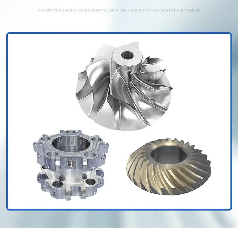
At GD Prototyping, we approach Axis Complex Part Machining as a process-planning problem rather than simply a 5-axis programming task. A successful strategy starts with material behavior and part geometry, then works backward into tooling, workholding, toolpath and inspection.
Why Titanium and Inconel Change the Machining Strategy
Titanium and nickel-based superalloys retain heat around the cutting zone more aggressively than conventional steels. Sandvik Coromant notes that poor thermal conductivity, high cutting temperatures and work hardening are major machining concerns for titanium and heat-resistant superalloys.
In Axis Complex Part Machining, these material characteristics become more difficult to manage because the tool may continuously change orientation around cavities, curved faces and undercuts.
| Machining factor | Titanium, especially Ti-6Al-4V | Inconel / nickel HRSA | Process implication |
| Heat | Concentrated near cutting edge | High cutting-zone temperature | Coolant access is critical |
| Tool wear | Adhesion, edge breakdown | Notching, abrasive wear | Stable engagement is required |
| Part behavior | Thin-wall deflection | High cutting forces | Rigid fixturing matters |
| Surface risk | Smearing, chatter | Work-hardened layer, tool marks | Avoid rubbing and worn tools |
| Multi-axis concern | Tool reach and heat | Tool load consistency | Optimize tilt and contact point |
Tooling: Control Engagement Before Increasing Speed
For Axis Complex Part Machining, tool rigidity usually matters more than aggressive cutting data.
Keep the Cutting System Short and Stiff
Long tool overhang increases deflection approximately with the cube of unsupported length, making deep pockets especially sensitive to chatter. A useful 5-axis strategy is therefore to tilt the spindle or workpiece so that a shorter cutter can reach the feature.
Practical priorities include:
• Use rigid carbide tooling matched to the alloy and operation.
• Minimize holder and cutter projection wherever geometry permits.
• Avoid dwelling or rubbing on Inconel surfaces because an already work-hardened layer increases subsequent tool load.
• Maintain consistent radial engagement rather than repeatedly loading and unloading the cutting edge.
• Separate roughing tools from finishing tools when surface integrity is critical.
Five-axis motion is valuable here because Axis Complex Part Machining can improve the cutting condition, not merely the tool's physical access.
Heat Management Is Also Dimensional Management
Coolant does more than protect the cutting edge. It removes chips, limits localized temperature rise and reduces the chance of hot-chip recutting. Sandvik specifically recommends coolant for HRSA machining to manage heat and chip evacuation.
For deep cavities and multi-face parts, we evaluate:
1. Coolant line-of-sight
A programmed tool angle may inadvertently block coolant from reaching the cutting interface.
2. Chip escape path
Recutting titanium or Inconel chips increases heat and can damage an already finished surface.
3. Roughing-to-finishing temperature
Precision finishing immediately after heavy roughing can introduce dimensional drift as the workpiece and fixture cool.
This was measurable in a GD Prototyping titanium aerospace project. A Ti-6Al-4V bracket measuring 187 × 94 × 62 mm contained 0.8 mm walls and critical bores specified at ±0.01 mm. During development, thermal growth affected bore position, so the process incorporated a stabilization period before final bore finishing.
That illustrates an important rule: in precision Axis Complex Part Machining, temperature belongs in the tolerance strategy.
Thin Walls and Deep Cavities Need Their Own Toolpath Logic
Thin sections should not be programmed as smaller versions of rigid features.
For titanium walls, machining pressure can elastically push the wall away from the cutter; the material then springs back after the tool passes. GD Prototyping's turbine-bracket case used temporary supporting stock and sequenced wall machining to reduce deflection on a 0.8 mm wall section.
For difficult features, consider:
• Leaving supporting material during roughing.
• Removing material symmetrically where practical.
• Reducing radial engagement during final wall passes.
• Using climb milling where appropriate.
• Orienting the 5-axis tool to reduce effective cutting length.
• Finishing critical features only after surrounding heavy material removal is complete.
Surface Finish Starts Before the Finishing Pass
A nominal Ra requirement cannot be solved simply by reducing stepover.
In Axis Complex Part Machining, surface quality depends on:
Machine stability + Tool condition + Engagement + Tool orientation + Remaining stock + Thermal state.
For curved surfaces, ball-nose cutters should be oriented so the effective contact point stays away from an unfavorable near-zero cutting-speed condition at the tool center. Stepover must then be selected according to allowable cusp height rather than appearance alone.
GD Prototyping's published titanium bracket achieved Ra 0.8 μm on bores and Ra 1.6 μm on external faces, with full dimensional verification by Zeiss CMM and surface profilometry.
3-Axis, 3+2 or Simultaneous 5-Axis?
More axes do not automatically produce a better part.
| Strategy | Best suited to | Main limitation |
| 3-axis | Open pockets, accessible faces | More setups for multi-face geometry |
| 3+2-axis | Angled holes and indexed faces | No continuous orientation during cutting |
| 5-axis simultaneous | Undercuts, sculptured surfaces, tightly related multi-face features | Greater programming and process complexity |
GD Prototyping operates 3-axis, 3+2-axis and full 5-axis machining, allowing the process to be selected around geometry rather than forcing every component onto the most complex machine. Its CNC service supports quantities from one part to 1,000+ pieces, general tight-tolerance capability down to ±0.05 mm, advertised surface roughness to Ra 0.2 μm, and process-dependent part lengths up to 118 inches.
For the titanium aerospace case above, full simultaneous 5-axis machining was selected because multiple undercut faces and tightly related bores made repeated datum transfers undesirable. The reported result was 50 parts delivered in 14 calendar days, with bore position maintained within the specified tolerance range.
DFM Rules We Check Before Machining
Good Axis Complex Part Machining starts before CAM programming.
During engineering review, we focus on:
• Deep pockets: Can depth-to-width ratio or access be improved?
• Internal corners: Does the radius allow a sufficiently rigid cutter?
• Thin walls: Is temporary supporting stock possible?
• Critical bores: Can they remain in one datum structure?
• Tolerances: Are ±0.01 mm-class requirements applied only where function requires them?
• Surface finish: Will polishing, coating or blasting change a critical dimension?
• Inspection: Can the feature be reached reliably by CMM or in-process probing?
GD Prototyping also lists Inconel 718 among its aerospace machining materials, alongside Ti-6Al-4V, aluminum alloys and 17-4 PH stainless steel.
Conclusion
Reliable Axis Complex Part Machining of titanium and Inconel comes from controlling the complete manufacturing system—not simply adding two rotary axes.
Tool rigidity, cutting heat, chip evacuation, wall stiffness, datum strategy, surface integrity and inspection all influence the final result. In many complex parts, the biggest advantage of 5-axis machining is therefore not speed; it is the ability to maintain better tool access and critical feature relationships with fewer setups.
If your design contains Ti-6Al-4V, Inconel 718, thin walls, deep cavities, compound angles or tightly related precision features, GD Prototyping can review the CAD model, material specification, tolerance scheme and surface requirements before machining begins. Visit GD Prototyping to discuss an appropriate Axis Complex Part Machining strategy for prototype or low-volume production.
FAQs
Q1. Does GD Prototyping provide Axis Complex Part Machining?
Yes. GD Prototyping provides 3-axis, 3+2-axis and full 5-axis CNC machining for complex parts with multi-face features, deep cavities, angled holes and curved surfaces.
Q2. Can GD Prototyping machine titanium parts?
Yes. GD Prototyping machines titanium alloys including Ti-6Al-4V for complex CNC parts requiring tight tolerances, thin-wall control and precision inspection.
Q3. Can GD Prototyping machine Inconel 718?
Yes. Inconel 718 is listed among GD Prototyping's aerospace machining materials for applications requiring high-temperature and mechanical performance.
Q4. What tolerances can GD Prototyping achieve?
GD Prototyping lists general CNC machining tolerances down to ±0.05 mm. More demanding features can be reviewed individually; a published titanium project included critical bores specified at ±0.01 mm.
Q5. What surface finishes are available?
GD Prototyping supports as-machined surfaces and secondary finishing such as polishing, blasting and other surface treatments. Published titanium machining data includes finishes down to Ra 0.8 μm on critical bores.
