


Automotive Steering Components: EV Design and Future Trends
Electric vehicles are changing the engineering priorities behind Automotive Steering Components. The shift from hydraulic steering toward electric power steering (EPS), ADAS-integrated control and steer-by-wire means steering hardware can no longer be treated as a purely mechanical system.
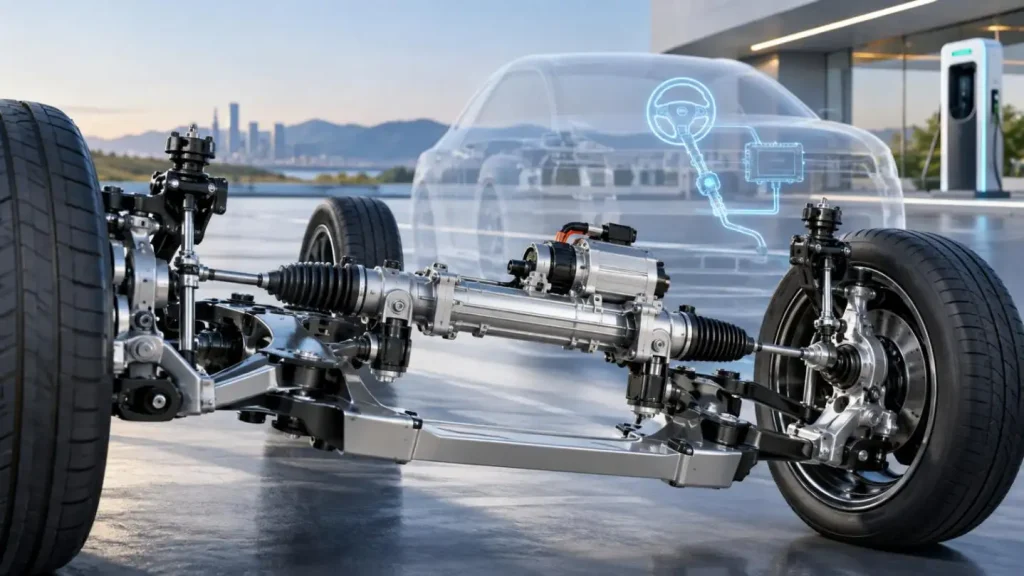
From a prototyping and manufacturing perspective, we see Automotive Steering Components becoming more integrated: structural housings must support motors and electronics, sensor locations require stable datum relationships, lightweight designs introduce thinner sections, and functional prototypes must increasingly represent production-intent materials and geometry.
What Counts as Automotive Steering Components?
Modern Automotive Steering Components combine mechanical, electromechanical and electronic elements, including:
• Steering racks, pinions and shafts;
• Columns, joints and tie-rod interfaces;
• EPS motor and gearbox housings;
• Actuator housings and mounting brackets;
• Torque and steering-angle sensor interfaces;
• ECU and electronics enclosures;
• Bearings, seals and precision mounting features.
For an EV steering system, these parts must work as an assembly. A housing bore that is individually within tolerance, for example, may still create alignment problems if its position relative to the motor axis, bearing seat or mounting datum is incorrect.
That makes tolerance stack-up and datum strategy as important as individual dimensional tolerances.
Key Design Requirements for EV Steering Components
The engineering requirements for Automotive Steering Components are increasingly interconnected.
| Design Factor | Engineering Concern | Manufacturing Impact |
| Dimensional accuracy | Bearing alignment, gear mesh, sensor position | Datum control, CMM inspection, stable fixturing |
| Stiffness | Steering response and actuator positioning | Material and wall-thickness optimization |
| Fatigue resistance | Repeated road and steering loads | Material condition, radii, stress concentration |
| Low mass | EV efficiency and axle mass | Aluminum, optimized pockets, thinner sections |
| NVH | EV cabins reveal mechanical noise more easily | Surface finish, bearing fits, gear interfaces |
| Thermal behavior | EPS motors and ECUs generate heat | Housing material, interfaces, heat paths |
| Functional safety | Steering is safety-critical | Redundancy, diagnostics and controlled interfaces |
The design target should therefore not simply be "machine this part to ±0.05 mm." Critical characteristics should be identified from function, assembly stack-up and validation requirements, while non-critical features receive economically appropriate tolerances.
Material Selection for Automotive Steering Components
Material selection depends on load path, stiffness, corrosion exposure, thermal requirements and production process.
Common choices include:
• Aluminum alloys for EPS housings, actuator housings and structural brackets where mass reduction and machinability are important.
• Carbon or alloy steels for shafts, racks, gears and highly loaded mechanical interfaces.
• Stainless steels where corrosion resistance is more critical.
• Engineering plastics for covers, guides, electrical interfaces and selected low-load components.
For prototype Automotive Steering Components, CNC machining is particularly valuable because engineers can evaluate parts in material conditions closer to the intended production component rather than relying only on appearance models.
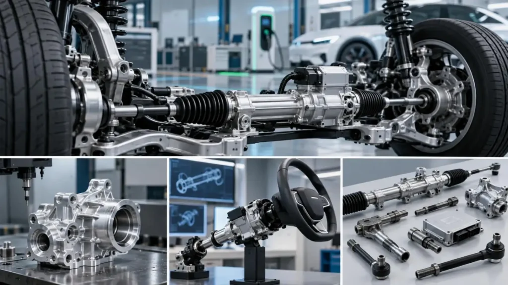
Why Steering Prototypes Are Difficult to Machine
A typical steering housing may combine bearing bores, threaded ports, sealing faces, sensor pockets, mounting bosses and deep cavities across several orientations.
The real manufacturing challenge is often not whether a feature can be cut, but whether its relationship to other features can be maintained after multiple setups.
5-Axis Machining Reduces Setup-Related Error
For complex Automotive Steering Components, 5-axis machining can provide several advantages:
• Fewer re-clamping operations;
• Improved positional relationship between multiple faces;
• Better access to angled holes and deep cavities;
• Shorter tool stick-out for difficult features;
• More consistent machining of complex housings.
At GD Prototyping, our published general CNC capability reaches ±0.05 mm under suitable conditions, with surface roughness down to Ra 0.2 μm. Maximum listed machining envelopes include 3,000 × 2,000 × 800 mm for 3-axis, 1,100 × 610 × 600 mm for 4-axis, and 1,000 × 800 × 600 mm for 5-axis CNC machining. Actual achievable tolerance depends on material, geometry, wall thickness, datum access and inspection requirements.
A Practical Example of Tight-Tolerance Automotive Machining
A useful comparison comes from an automotive sensor-housing project completed by GD Prototyping.
The 6061-T6 aluminum component measured 87 × 54 × 32 mm, with minimum wall sections of 1.2 mm. Its critical Ø22 mm bore was specified at +0.010/-0.000 mm, with an Ra 0.8 μm bore finish. The project involved 150 parts manufactured by 5-axis CNC milling and turning.
Although this was a sensor housing rather than a steering housing, the manufacturing problem is directly relevant to prototype Automotive Steering Components: thin walls, precision bores and multi-datum geometry require controlled fixturing, toolpath planning and inspection rather than simply selecting a high-accuracy machine.
Prototype Strategy: Match the Process to the Validation Question
Not every steering prototype needs the same manufacturing process.
For fit and packaging:
SLA, SLS or MJF can quickly validate envelopes, brackets and assembly interfaces.
For functional mechanical testing:
CNC machining is better suited to production-relevant aluminum, steel and engineering plastics.
For shafts and rotational parts:
CNC turning provides an efficient route for concentric diameters, shoulders, threads and bearing interfaces.
For pilot builds:
Low-volume CNC production helps engineers verify assembly consistency before committing to tooling.
A practical Automotive Steering Components development sequence is:
CAD → Tolerance review → Material selection → DFM → Prototype → Dimensional inspection → Functional test → Design revision → Pilot build
At GD Prototyping, DFM review focuses not only on whether the CAD model is machinable, but also on tool access, datum selection, wall stability, tolerance concentration, finishing allowances and inspection strategy.
EPS and Steer-by-Wire Change the Hardware Requirements
EPS retains a mechanical steering path while adding electric assistance. Steer-by-wire goes further by replacing the fixed mechanical link between steering input and road-wheel actuation with sensors, software and electromechanical actuators.
That changes the requirements for Automotive Steering Components. Actuator housings, motor interfaces, sensor mounts and electronics packaging become more critical, while redundancy and functional safety must be considered at system level.
This transition has already entered series production: ZF began supplying a steer-by-wire system for the NIO ET9 in 2025, including a steering-wheel actuator, redundant steering-gear actuator and associated software.
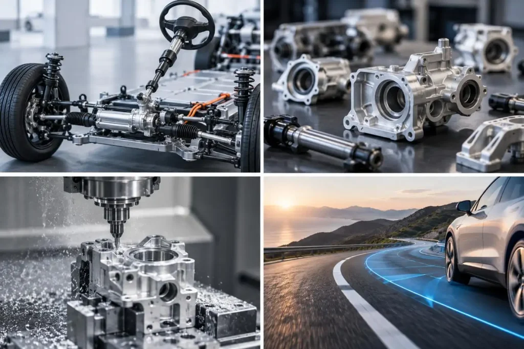
Where Automotive Steering Components Are Heading
Future Automotive Steering Components will increasingly be shaped by three developments:
• Steer-by-wire: greater integration of sensing, actuation and software.
• Software-defined chassis control: closer coordination between steering, braking, suspension and ADAS.
• Integrated lightweight structures: fewer parts, more functions per housing, and more complex machined geometry.
For engineering teams, these trends make rapid physical iteration increasingly valuable. A CAD model can predict geometry, but functional prototypes reveal assembly behavior, tolerance interaction, tool-access problems and manufacturing risk.
From Steering Design to Functional Hardware
Developing reliable Automotive Steering Components requires more than achieving nominal dimensions. Geometry, material, tolerance strategy, machining sequence, finishing and inspection must support the intended function as one engineering system.
For teams developing EPS housings, actuator parts, brackets, shafts or related EV steering prototypes, GD Prototyping can support the transition from CAD and DFM review to CNC-machined functional prototypes and low-volume builds using 3-, 4- and 5-axis machining, CNC turning and complementary rapid-prototyping processes.
If you are evaluating a new Automotive Steering Components design, sharing the CAD model, material requirement and critical dimensions early allows the manufacturing route and tolerance risks to be reviewed before pilot production—often when design changes are still relatively inexpensive.
FAQs
Q1. Can GD Prototyping manufacture Automotive Steering Components prototypes?
Yes. GD Prototyping can produce prototype steering housings, brackets, shafts, actuator parts, sensor housings, and related mechanical components using CNC machining and other rapid prototyping processes.
Q2. What CNC processes does GD Prototyping use for Automotive Steering Components?
GD Prototyping provides 3-axis, 4-axis, 5-axis CNC milling and CNC turning for precision metal and plastic steering prototypes.
Q3. What CNC tolerance can GD Prototyping achieve?
General CNC machining capability can reach approximately ±0.05 mm under suitable conditions. Tighter tolerances depend on material, geometry, feature size, fixturing, and inspection requirements.
Q4. Can GD Prototyping machine complex steering housings?
Yes. 5-axis CNC machining is suitable for housings with multi-face features, angled holes, bearing bores, mounting interfaces, and complex internal or external geometry.
Q5. What materials can be used for Automotive Steering Components prototypes?
Common prototype materials include aluminum alloys, steels, stainless steels, and engineering plastics. Selection depends on strength, stiffness, weight, corrosion resistance, thermal behavior, and test requirements.
