


High-Speed Milling Strategies for Automotive Aluminum CNC Machining Components
High-speed milling is a solution for the specific needs of Automotive Aluminum CNC Machining Components. These needs may be lightweight, complex designs and highly repeatable, reliable precision with well-defined surface quality. Common applications for this technology include the enclosures for EV batteries, housings for inverters, motors, and various engine parts, along with cooling plates, suspension brackets, housings for various sensors, and other components.
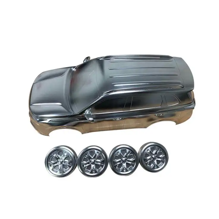
High-speed machining is a balance of many variables beyond simply increasing spindle speed. Achieving high-speed machining requires a balance of spindle RPM, feed, chip load, and tool and workholding engagement, as well as fluid cooling and efficient chip removal. The goal of such a balance is to quickly and efficiently remove Aluminum, with high precision while avoiding the material sticking to the cutting edge of the tool (called built-up edge), burrs, deformation of the workpiece, and dimensional instability.
What is High-Speed Milling for Automotive Aluminum CNC Machining Components?
High-speed milling is the combination of high-speed spindle rotation, and precise control of tool engagement and chip formation. This process typically includes:
• An optimal high spindle speed
• Uniform feed per tooth
• Minimal radial engagement
• Continuous tool paths
• Effective chip removal
• Minimal runout of the tool and holder
• High rigidity of the machine and rapid acceleration
Three key calculations define starting parameters for the process.
Spindle speed: n = Vc × 1000 ÷ πD
Feed rate: Vf = n × z × fz
Material removal rate: Q = ap × ae × Vf
The appropriate factors must be considered for the Aluminum grade, cutter diameter, flute count, tool overhang, machine capability, wall thickness, and part geometry.
Typical Uses for Aluminum in the Automotive Industry
| Component | Description | Milling Challenge |
| EV battery enclosure | Very large and flat | Reduce distortion during milling and lower overall cycle time |
| Motor housing | Coaxial features | Ensure coaxial surfaces |
| Inverter housing | Very thin walls and thermal interfaces | Ensure flatness and minimize distortion |
| Cooling plate | Features and sealing grooves | Reduce burrs and seams/leakage |
| Suspension bracket | Highly loaded and complex shapes | Control dimensions during rough machining |
| Sensor housing | Very small features and high cosmetic surfaces | Enhance small feature machining and surface finish |
These components tend to have a combination of high cosmetic surfaces, large thin sections, deep pockets, tightly controlled spatial features, and angled holes in multiple directions.
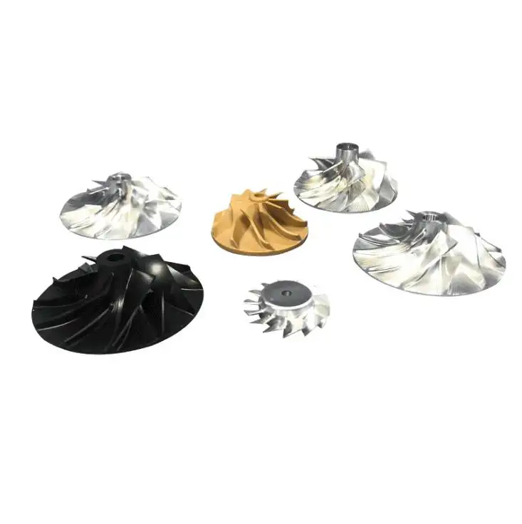
High-Speed Aluminum Tooling
High-speed aluminum tooling requires a positive tool geometry with razor sharp edges and a sufficient chip space with polished flutes. Tooling with reduced tool overhang is also a positive design feature.
Solid carbide tooling is the standard for high-speed aluminum machining. An uncoated highly polished tool can also reduce aluminum build-up on the tool, and a DLC coating can also reduce the friction in a production environment. High-silicon cast aluminum is more abrasive and may require an added wear-resistant tool.
Due to high spindle speeds, tool balance and run-out are critical. Excessive run-out can result in poor surface finish and critical dimensions.
Roughing Strategies for Automotive Aluminum CNC Machining
Large volume removals of aluminum can be accomplished with dynamic machining. The toolpath is designed with a consistent cutting angle, eliminating large-volume cuts in the corners of the machining stock.
Key advantages include:
• Lower cutting-load variation
• Reduced full-width slotting
• Higher usable axial depth
• More stable chip thickness
• Improved tool-life consistency
• Higher material removal efficiency
Feed rate should not be increased independently. Spindle speed, feed per tooth, radial width, axial depth, flute count, and chip evacuation must work as one system.
Roughing should create a uniform finishing allowance. Variations in the stock can result in abrupt changes of cutting force during finishing. This can create movement of thin walls, irregular finishing marks, and dimension variations.
Finishing Precision Automotive Features
Sealing faces, bearing bores, mounting surfaces, and appearance areas require a dedicated finishing strategy.
Useful practices include:
• Use climb milling where appropriate
• Separate roughing and finishing tools
• Maintain a constant stepover
• Control tool runout
• Use continuous passes on critical contours
• Avoid unnecessary entries on sealing surfaces
• Match corner radius and stepover to the required finish
A low Ra value cannot be achieved through spindle speed alone. Machine vibration, cutter condition, runout, feed rate, toolpath continuity, and material stability all affect the final surface.
Controlling Thin-Wall Deformation
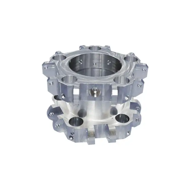
Thin-wall distortion is a major risk in Automotive Aluminum CNC Machining Components, particularly battery housings, electronic enclosures, and lightweight structural brackets.
Material removal should be balanced and carried out evenly from opposite sides, where possible. Leaving unmachined areas on the opposite sides can cause uneven residual stress and twisting of the component once it has been released from the workholding.
The following can be used to help reduce cutting forces.
• Sharp tools
• Smaller radial engagement
• Stable chip thickness
• Short tool length
• Multiple light cuts
• Proper support of the workpiece
Workholding methods should allow for the complete dispersion of clamping forces without damaging thin sections. The type of workholding system used (soft jaws, modular fixtures, vacuum workholding, etc.) should be based on the size, geometry, and available surfaces of the workpiece.
Removing Chips and Preventing Built-Up Edge
Aluminum chips sometimes stick to the cutting edge or end up in deep cavities in the workpiece. Chips that are recut can cause scratches to the surface finish, generate additional heat, and cause premature failure of the cutting tool.
| Problem | Most Likely Cause | Course of Action |
| Built-up edge | Tool is dull or lubrication is poor | Sharpen tool and improve lubrication |
| Scratched surface | Recut chip | Reposition air blast or chip removal coolant |
| Excessive burrs | Tool is worn or incorrect method | Tool and method inspection |
| Chatter marks | Tool engagement is unstable | Shorten the tool and improve the method |
| Local overheating | chips are not removed | Improved removal and reduce recutting of chips |
Choosing Between Types of 3-Axis, 3+2, and 5-Axis Milling
3-Axis milling is the most cost effective for flat plates and housings, and open pockets. 4-Axis is useful for machining rotational features, and side faces. When features are at angles, 3+2 is useful, and when contours are more complex, and access is restricted, then 5-Axis is required.
Five-axis machining is not required for every part. Its main value is reducing setups, improving positional relationships, allowing shorter tools, and limiting accumulated alignment error in complex Automotive Aluminum CNC Machining Components.
Quality Control and Production Cost
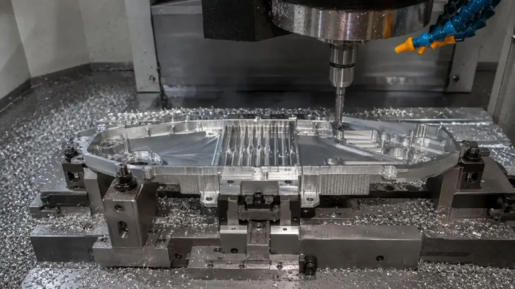
High-speed machining must control more than cycle time. Inspection may include:
• Flatness and profile
• Hole diameter and position
• Coaxiality
• Sealing-groove dimensions
• Surface roughness
• Burrs and technical cleanliness
• Batch-to-batch consistency
First-article inspection, CMM measurement, in-process probing, tool-life management, SPC, and critical-dimension reports can support production stability.
Costs arise from material removal, number of setups, tool usage, thin-wall risk, inspection, finishing, and scrap. The optimal process achieves stable quality over an efficient total cycle time. It is not defined as the process with the highest spindle speed.
Final Words
High-speed milling that is reliable and consistent requires a balance of machine and cutting tool dynamics, toolpaths, fixtures, cooling, and inspection. Even removal of material and an optimal process for chip removal and chip clearance are of greater importance than just using a high spindle speed.
Are you designing new Automotive Aluminum CNC Machining Components? GD Prototyping can help you design and optimize your component. Drawings and files can be submitted and an aluminum grade, desired quantity, machining tolerances, and surface finish along with inspection criteria can be added. The engineering team will evaluate the request and advise on the most effective machining solution for prototypes, small production runs, or final production components.
FAQs
Q1. Can GD Prototyping achieve Ra 0.2μm surface roughness?
Achieving Ra 0.2 μm is possible with appropriate materials and design. Ultimately, the surface finish is influenced by part and feature design, surface machining tool, machine configuration, part rigidity, and any additional surface finish operation.
Q2. Which CNC machining services does GD Prototyping offer?
GD Prototyping offers 3-axis, 4-axis, 3+2-axis, and simultaneous 5-axis CNC milling, as well as CNC turning.
Q3. What are the machining compatible aluminum alloys for automotive applications?
Typically, the options include the aluminum alloys: 5052, 6061, 6082, 2024, 5083, 7050, 7075, and ADC12. Other alloys may be considered depending on the specific project.
Q4. Can GD Prototyping machine the aluminum thin walled automotive parts?
For sure. GD Prototyping can analyze toolpath, sequences of machining, fixturing supports, and allowances for finishing in order to mitigate the deformation of thin walled housings and structural parts.
Q5. What are the machining tolerances of GD Prototyping?
For some metals, tolerances of approximately ±0.05 mm may be possible. The absolute tolerances that may be considered depend on part size, part geometry, the condition of the material, feature accessibility, and inspection requirements.
