


Aluminum CNC Enclosure Machining: How to Control Thin-Wall Deformation
Thin-wall deformation in Aluminum CNC Enclosure Machining can be controlled through stable material selection, uniform wall design, balanced material removal, low-stress toolpaths, optimized fixturing, controlled cutting conditions, staged finishing and free-state inspection.
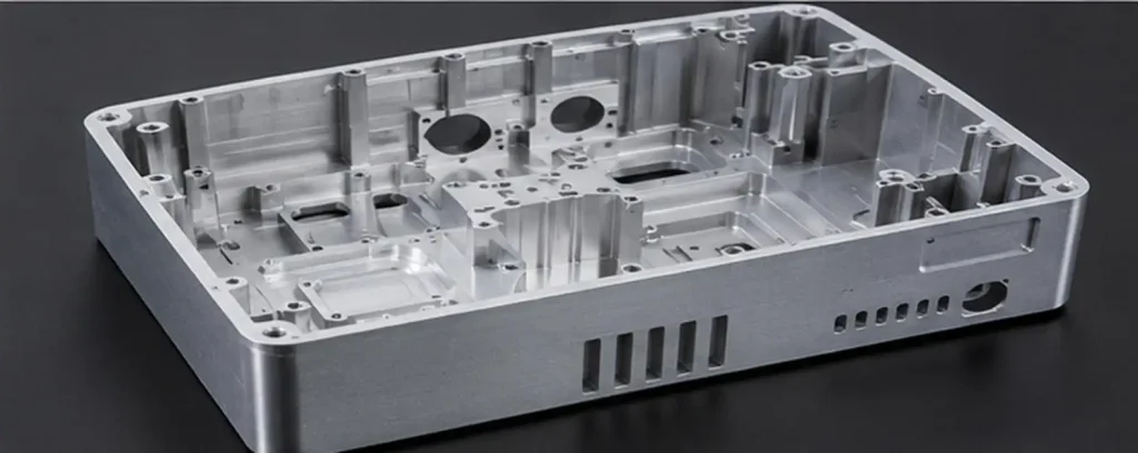
Deformation is rarely caused by one factor. It usually results from the combined effects of residual material stress, cutting force, clamping pressure, thermal expansion and insufficient structural rigidity. For electronic, medical, communication and automotive enclosures, even minor distortion can cause PCB misalignment, connector interference, uneven gasket compression or poor thermal contact.
What Is Thin-Wall Deformation?
Thin-wall aluminum enclosures often contain deep cavities, long sidewalls, narrow frames, connector openings, heat-dissipation features and precision mounting surfaces. Because much of the original stock is removed, the remaining structure has limited resistance to bending.
Common deformation modes include:
| Deformation | Typical appearance | Possible consequence |
| Warping | Base or cover bends upward | Sealing or assembly failure |
| Wall expansion | Long walls move outward | Profile and dimensional errors |
| Wall contraction | Walls spring inward after unclamping | PCB or component interference |
| Twisting | Diagonal corners differ in height | Flatness and assembly instability |
| Local indentation | Distortion near clamps | Cosmetic or dimensional defects |
| Thermal drift | Dimensions change during machining | Unstable finishing accuracy |
Why Do Thin Aluminum Enclosures Deform?
Residual Stress in Aluminum Stock
Rolled plate, extruded stock and heat-treated aluminum may contain internal stress. When material is removed heavily from one side, the original stress balance changes and the enclosure may bend.
The risk depends on:
• Raw material flatness and manufacturing route
• Heat-treatment condition
• Direction and amount of material removal
• Final wall and base thickness
• Time allowed between roughing and finishing
Low Wall Rigidity
Thin walls can deflect under relatively low cutting forces. During machining, the tool may push the wall away from its programmed position. After the cutter passes, the wall springs back, producing dimensional error or surface waviness.
Excessive Clamping Force
A part may measure correctly while held in a fixture but deform after release. Concentrated clamping pressure can pre-bend a sidewall or base plate. For this reason, stronger clamping does not always improve Aluminum CNC Enclosure Machining accuracy.
Cutting Heat
Worn tools, poor chip evacuation and excessive tool engagement generate localized heat. Because aluminum expands as its temperature rises, finishing a warm enclosure can result in dimensional drift after cooling.
Selecting Aluminum for Thin-Wall Enclosures
Material selection should consider more than strength.
| Alloy | Machining characteristics | Thin-wall considerations |
| 6061 | Balanced machinability, strength and anodizing response | Common choice for electronic and industrial housings |
| 5052 | Good corrosion resistance but relatively soft | Requires careful burr and clamping control |
| 2024 | High strength and good machinability | Corrosion protection should be evaluated |
| 7075 | High strength and rigidity | Material cost and residual stress require attention |
| 6082 | Balanced structural and machining properties | Suitable for industrial enclosures |
Raw material condition, thermal performance, corrosion environment, anodizing requirements and production volume should also be reviewed before machining.
DFM Guidelines for Reducing Deformation
Effective deformation control begins during design.
Maintain Uniform Wall Thickness
Abrupt wall-thickness changes create uneven rigidity and cutting loads. Sidewalls and base sections should remain as consistent as possible. Unnecessarily thin regions should be avoided, especially near connectors, threaded holes and sealing surfaces.
Use Practical Corner Radii
Very small internal radii require small or extended tools. These tools are more likely to vibrate and deflect. Larger internal radii allow the use of shorter, more rigid cutters.
Include Ribs Judiciously
Although ribs can enhance the stiffness of an enclosure, they can also create unfavorable pockets, limit access to machining tools, and interfere with the removal of chips if they are poorly placed. As ribs do provide some stiffening, the balance of stiffness versus the ease of machining should be considered.
Implement Tight Tolerances with Discrimination
Apply strict tolerances to:
• Holes for locating the PCB
• Connector openings
• Sealing grooves
• Surfaces for thermal contact
• Threaded surfaces
• Facing surfaces
Avoid the notion that strict tolerances for surfaces of an enclosure will improve its performance. Rather, you will likely increase costs with scantly any effect on performance.
Machining Strategies for Thin-Wall Stability
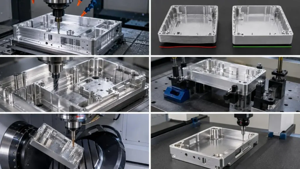
A reliable Aluminum CNC Enclosure Machining process usually separates roughing, semi-finishing and finishing.
A typical sequence is:
- Remove most material during balanced roughing.
- Leave uniform stock on walls and critical surfaces.
- Allow residual stress to redistribute.
- Flip or re-clamp the enclosure.
- Semi-finish the cavity and external profile.
- Complete critical dimensions with light finishing passes.
Material should be removed symmetrically whenever possible. Stress imbalance can be minimized by layering and switching sides while machining.
Temporary ribs, sacrificial bases, support posts or peripheral frames can preserve rigidity while the cavity is being produced. These features are removed only after critical surfaces are finished.
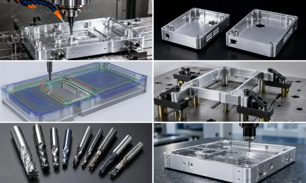
Low-radial-engagement toolpaths are also useful because they maintain a more stable cutting load. Thin walls should be finished through several light passes rather than one heavy final cut.
Tooling and Fixturing Considerations
Sharp aluminum-specific tools with polished flutes help reduce cutting force and prevent chip adhesion. Tool overhang should be kept as short as geometry permits.
| Factor | Control objective | Risk if poorly controlled |
| Tool diameter | Balance access and rigidity | Deflection and vibration |
| Axial depth | Remove material progressively | Excessive local force |
| Radial engagement | Stabilize tool load | Wall displacement |
| Feed and speed | Avoid rubbing or overload | Heat, chatter or tool wear |
| Coolant and air | Control heat and remove chips | Recutting and surface damage |
Fixtures should distribute force over a wide area. Machined soft jaws, multi-point supports and sacrificial plates are commonly used. Vacuum fixtures may suit large covers, but suction must not pull the part into a distorted shape.
Before final inspection, the enclosure should be released from heavy clamping and measured in a free or assembly-representative condition.
How Multi-Axis Machining Helps
Three-axis machining is adequate for typical recesses and flat features. A 3+2-axis variant reduces the number of setups needed for inclined surfaces and lateral and internal holes and connectors. Five-axis machining allows for better tool placement for extremely complex surfaces and allows for potentially smaller tool setups.
While Five-axis machining allows for the potential to reduce deformation due to the improved rigidity from the reduction of setups, it does not remove the residual stress.
Inspection and Surface Finishing
Critical inspection items include flatness, profile, hole position, wall thickness, sealing grooves, mating gaps and surface roughness. CMM inspection, height gauges, contour measurement, roughness testing and assembly trials may all be required.
Surface finishing must also be considered during DFM. Anodizing can change critical dimensions, while sandblasting, polishing and brushing may affect edges or visual consistency. Conductive grounding areas, threads, sealing faces and precision fits may require masking or dimensional compensation.
How GD Prototyping Supports Aluminum CNC Enclosure Machining
GD Prototyping supports projects from functional prototypes to low-volume and end-use production using in-house 3-axis, 4-axis, 3+2-axis and simultaneous five-axis machining.
Available aluminum options include 6061, 5052, 2024, 7075, 5083, 6082, 3003 and 1100. Finishing options include as-machined surfaces, anodizing, sandblasting, polishing and brushed finishes.
Under suitable material and geometry conditions, machining capability can reach tolerances of approximately ±0.05 mm and surface roughness down to Ra 0.2 μm. These values are not automatic for every thin-wall enclosure; achievable results depend on part size, wall thickness, material condition, fixturing and inspection requirements.
With an in-house machine shop, 24/7 production scheduling and one-to-one engineering support, GD Prototyping can review drawings, tolerances and deformation risks before manufacturing.
Building More Stable Thin-Wall Aluminum Enclosures
Reliable Aluminum CNC Enclosure Machining requires coordinated control of material, geometry, toolpaths, fixturing and inspection. Uniform walls, balanced roughing, light finishing and free-state measurement are often more important than machine accuracy alone.
GD Prototyping provides practical DFM reviews for aluminum enclosure prototypes and production parts. Submit your enclosure drawings to evaluate wall thickness, machining sequence, tolerances, surface finishing and inspection requirements before production begins.
FAQs
Q1. Does GD Prototyping have Aluminum CNC Enclosure Machining?
Yes. GD Prototyping offers Aluminum CNC Enclosure Machining for functional prototypes and production parts. They provide 3/4/5-axis CNC machining for a variety of applications.
Q2. Can GD Prototyping machine thin-wall aluminum enclosures?
Yes. GD Prototyping is able to design thin walls, deep cavities, and ribs / connectors / seals / mounts. The engineering team reviews the deep features for concerns on how the material will be held, how the tools will access the features, and how the material will deform while being machined.
Q3. What aluminum alloys are allowed for CNC enclosure machining?
Aluminum 6061, 5052, 2024, 7075, 5083, 6082, 3003, and 1100 are all acceptable aluminum alloys. When choosing your material, consider the balance of the following: strength, machining, corrosion, thermal, and surface finish.
Q4. What tolerances can GD Prototyping achieve?
Depending on the material and geometry, GD Prototyping can achieve tolerances around ±0.05 mm. The actual tolerances are dependent on wall thickness, feature geometry, the material, and inspection requirements.
Q5. What is the surface roughness for machined aluminum enclosures?
Surface roughness for aluminum enclosures is dependent on the machining and feature requirements, but can be as low as Ra 0.2 μm. This capability cannot be applied to all surfaces of an enclosure.
