
5 Axis CNC Machining Services for Aerospace Components: A Turbine Bracket Case Study
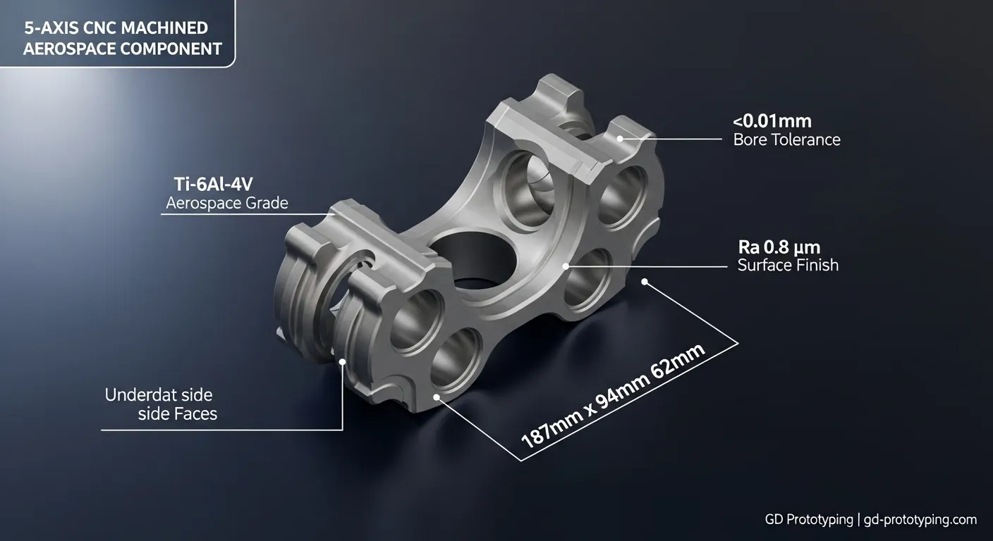
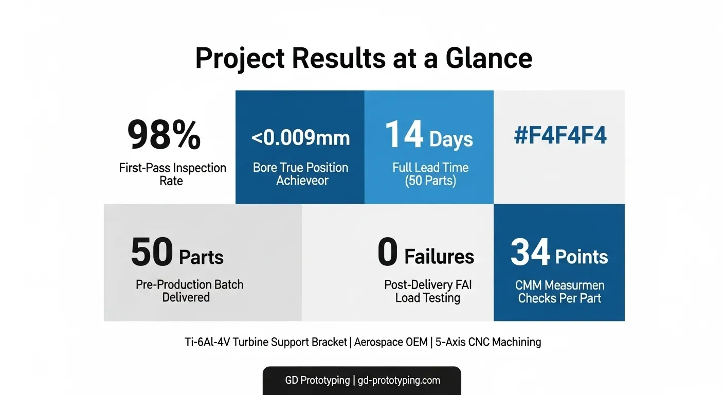
We used full simultaneous 5-axis CNC machining on a European aerospace OEM's titanium turbine support bracket. The part was Ti-6Al-4V, 187mm x 94mm x 62mm, with a ±0.01mm critical bore tolerance. We delivered 50 validated parts in 14 days, achieving a 98% first-pass inspection rate and zero field failures in post-delivery functional testing.
Introduction
An aerospace procurement engineer reached out to us with a problem we see often: a supplier had rejected their turbine bracket drawing after three rounds of DFM review. The geometry had five undercut faces, a 14mm deep internal cavity with 0.8mm wall sections, and a bore cluster that needed to hold ±0.01mm across a 62mm span.
With conventional 3-axis machining, that part requires at least four separate setups. Every setup change introduces datum shift. On a titanium part with tolerances that tight, even a 0.008mm datum error is enough to fail inspection.
Our team offered a different path: full simultaneous 5-axis CNC machining from a single fixture. That single decision changed everything about how this project went.
Project Overview
The client was a Tier-1 avionics and structural component supplier based in Germany, developing a next-generation turbine support bracket for a narrow-body commercial aircraft program. The bracket mounts between the engine nacelle frame and the core engine casing. It carries both static structural load and vibration cycles during flight, so dimensional accuracy and surface integrity are not optional.
They needed 50 prototyping and pre-production parts for FAI (First Article Inspection) qualification and functional load testing. The delivery window was non-negotiable: 14 calendar days from drawing approval.
They came to GD Prototyping after their previous supplier failed to hold the bore position tolerance across two trial batches.
Technical Specifications
| Parameter | Detail |
|---|---|
| Material | Titanium Grade 5 (Ti-6Al-4V, AMS 4928) |
| Part Name | Turbine Support Bracket |
| Dimensions | 187mm x 94mm x 62mm |
| Critical Bore Tolerance | ±0.01mm |
| General Tolerance | ±0.03mm |
| Wall Thickness (minimum) | 0.8mm |
| Surface Finish | Ra 0.8 μm (bore), Ra 1.6 μm (external faces) |
| Quantity | 50 parts (pre-production) |
| Lead Time | 14 calendar days |
| Primary Process | Full Simultaneous 5-Axis CNC Milling |
| Secondary Process | CNC Turning (boss features), Manual deburring |
| Machine Used | DMG Mori DMU 65 monoBLOCK |
| CAM Software | Siemens NX CAM |
| Inspection Method | Zeiss CMM, surface profilometer |
Machining Process
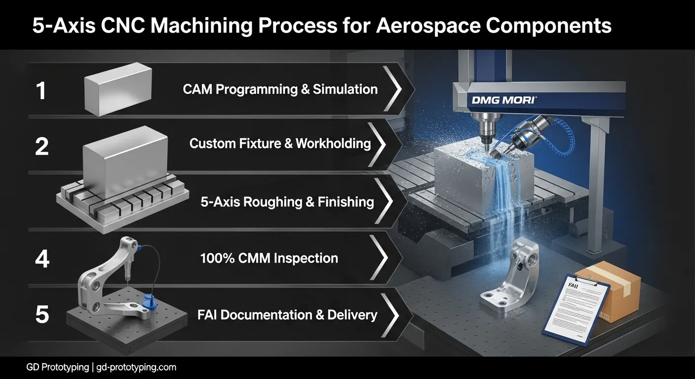
Here is how we took this bracket from raw titanium billet to inspection-ready part in 14 days.
Step 1: CAM Programming and Toolpath Simulation
Our CAM engineer built the full toolpath in Siemens NX CAM. Before cutting a single chip, we ran a complete in-software collision simulation. This step found two tool-holder clearance conflicts on the internal cavity approach angle. We resolved them by adjusting the tool tilt axis to 12 degrees offset and switching from a standard BT40 holder to a slim-nose shrink-fit holder.
Step 2: Fixture Design and Workholding
We designed a custom modular titanium fixture that clamped the billet at the base flange zone, keeping all five critical faces open for tool access. Workholding rigidity is not negotiable with titanium: the material's low thermal conductivity means heat builds fast, and any chatter during cutting accelerates tool wear and can cause micro-surface damage that fails the Ra 0.8 μm bore spec.
Step 3: Roughing
We used a 12mm carbide 4-flute end mill for roughing, removing material in 1.5mm axial depth passes at 180 m/min cutting speed. Coolant was high-pressure through-spindle flood at 80 bar to clear titanium chips and suppress heat. We left 0.25mm stock on all walls for the finishing pass.
Step 4: Semi-Finishing and Finishing
For the complex undercut faces and the internal cavity, we ran full 5-axis simultaneous paths using a 6mm ball-nose carbide cutter with a 0.1mm stepover. The DMG Mori's RTCP (Rotational Tool Center Point) function kept the tool tip precisely on the curved surface normal throughout all axis rotations, eliminating the positional error that would occur if we repositioned the part.
Final bore finishing used a 10mm solid carbide reamer running at 25 m/min with a 0.02mm/rev feed. That combination held the bore diameter to within ±0.008mm across all 50 parts.
Step 5: Deburring and Surface Prep
Manual deburring was done on all internal edges with titanium-compatible carbide burrs. Parts were then cleaned in an ultrasonic bath before inspection.
Challenges and Solutions
This project had two serious technical problems. Here is what happened and how we fixed each one.
Challenge 1: Thin Wall Deformation During Internal Cavity Machining
The 0.8mm wall section at the base of the internal cavity was the most dangerous feature on this part. During our first two test cuts on pre-production samples, the wall deflected by 0.04mm under tool pressure. That pushed it outside the ±0.03mm general tolerance.
What we tried first (and why it failed): We reduced cutting depth to 0.5mm axial passes. The deflection improved slightly, but not enough. The wall still measured 0.036mm out of position on one side after machining.
The actual fix: We redesigned the toolpath sequence so the cavity walls were rough-cut in a climb-milling direction only, which reduces the radial cutting force pushing against the wall. We also added a support strategy where we left 0.15mm extra stock on the opposite wall face during roughing to act as a temporary brace, removing it only during the final finishing pass. After this change, all 50 production parts measured within ±0.018mm on the wall position, well inside spec.
Challenge 2: Bore Position Drift Across a 62mm Span
The bracket has three co-axial bores spaced across a 62mm span. The client's FAI requirement was that all three bore centers stay within ±0.01mm true position relative to the primary datum. This is tight for a titanium part, because the material's low conductivity causes thermal growth during machining that moves datums.
What we tried first (and why it failed): In our first batch of 10 parts, we machined all three bores in the same continuous cycle. When the CMM measured those parts, the third bore in the sequence showed +0.013mm true position error - just outside spec. We traced the error to thermal growth in the fixture and the workpiece during the 38-minute cutting cycle.
The actual fix: We added a mid-cycle dwell step of 8 minutes between roughing the bore cluster and finishing it, with coolant flooding running continuously. This stabilized the part temperature to within 1.5°C of ambient before finishing. We also re-measured the datum reference every 5 parts using the machine's touch probe and applied an automatic offset correction. After this protocol, bore true position across all remaining 40 parts stayed within ±0.009mm.
Quality Control
Every part went through a three-stage inspection protocol before shipping.
Stage 1: In-Process Touch Probe Inspection
The DMG Mori's integrated Renishaw touch probe checked datum position and bore diameter after each finishing operation, directly on the machine table. This let us catch any drift before the part was unclamped.
Stage 2: CMM Full Dimensional Report
We measured 100% of the 50 parts on a Zeiss Contura CMM. Each report covered 34 measurement points including:
- 3 bore diameters and true positions
- 5 face-to-face parallelism values
- Minimum wall thickness at 6 cavity points
- 4 thread-form features
Stage 3: Surface Finish Verification
We used a Mitutoyo SJ-210 profilometer on each bore and 3 external faces per part. All 50 parts passed Ra 0.8 μm on bores and Ra 1.6 μm on external faces.
The complete CMM data package, material certs, and machine logs were delivered with the shipment as part of the FAI documentation package.
Results
The numbers tell the story clearly:
- Lead time: 14 calendar days from drawing approval to delivery, as agreed
- First-pass inspection rate: 98% (49 of 50 parts passed all 34 measurement points on first inspection; 1 part required a light bore re-ream)
- Bore true position: All 50 parts within ±0.009mm against a ±0.01mm requirement
- Wall thickness conformance: 100% of parts within ±0.018mm against ±0.03mm spec
- Surface finish: 100% pass rate on all Ra measurements
- Post-delivery functional testing: 0 failures across 50 parts during the client's FAI load and vibration testing program
- Client reorder: The client placed a 200-part follow-on order within 3 weeks of delivery
Why 5-Axis CNC Machining Was Used
This part could not be made reliably any other way. Here is a quick comparison:
Casting: Investment casting can produce titanium near-net shapes, but the dimensional accuracy on bores and tight-tolerance faces requires extensive post-machining anyway. For a 50-part pre-production run, casting tooling cost alone would have been $8,000-$12,000 USD with a 6-week lead time before the first part.
3D Printing (DMLS/SLM): Titanium additive manufacturing can produce complex geometries, but it leaves internal stresses that affect dimensional stability and bore cylindricity. Post-processing still requires machining to achieve Ra 0.8 μm bore finish. For flight-critical structural components, the material traceability and as-built property documentation requirements add weeks to validation timelines.
3-Axis CNC Machining: Technically possible with 4+ setups, but each re-fixturing step introduces datum shift risk. On a part with ±0.01mm bore true position, that risk is unacceptable. Our CNC machining case studies show why single-setup 5-axis is the right choice for complex aerospace geometries.
Full simultaneous 5-axis machining from GD Prototyping eliminated the re-fixturing problem entirely, compressed the lead time, and gave the client a complete CMM-documented quality record with every part.
FAQ
What materials can you machine for aerospace components using 5-axis CNC?
We regularly machine titanium Ti-6Al-4V (AMS 4928), aluminum 7075-T6 and 6061-T6, Inconel 718, and stainless 17-4 PH for aerospace applications. Material certifications and full traceability documentation are available for all aerospace-grade stock. Visit our CNC machining services page for the full material list.
What tolerance can you hold on 5-axis aerospace parts?
Our standard general tolerance is ±0.05mm. For critical bore features and position tolerances on 5-axis parts, we routinely hold ±0.01mm using in-process touch probe verification and 100% CMM inspection. Surface finish down to Ra 0.2 μm is achievable on finished bores.
How long does it take to machine aerospace CNC prototype parts?
Lead times depend on part complexity and quantity. For the bracket in this case study, 50 parts shipped in 14 days. Simple prismatic parts in small quantities can ship in 5-7 days. Contact us for a project-specific timeline.
Do you provide FAI documentation and material certifications?
Yes. We provide full CMM inspection reports, material mill certificates, process logs, and surface finish verification data as standard with aerospace orders. This documentation package supports AS9100 and customer-specific FAI requirements.
What's the difference between 3+2-axis and full simultaneous 5-axis machining?
In 3+2 machining, the two rotary axes lock the part at a fixed angle while three linear axes do the cutting. It's faster and cheaper for many features. In full simultaneous 5-axis, all five axes move at the same time, which is essential for undercut geometries, complex curved surfaces, and tight true-position tolerances across multiple features. We use both approaches depending on part geometry and tolerance requirements.
Conclusion
This titanium turbine bracket project shows exactly what full simultaneous 5-axis CNC machining can do that no other process can match at prototype and pre-production scale: single-setup accuracy on complex geometry, complete CMM documentation, and a 14-day delivery window.
If your aerospace component has tight bore tolerances, thin walls, undercut faces, or multi-axis features, our team at GD Prototyping is ready to review your drawing. We'll give you a DFM analysis and quote within 12 hours.
Get a Free Quote for Your Aerospace CNC Machining Project
Browse our CNC machining prototype case studies to see more real-world examples of precision parts we've produced for aerospace, medical, and automotive clients.