
3D Printing Tolerances: A Process‑by‑Process Chart and Guide
3D printing has unlocked unprecedented design freedom for engineers. It allows for the creation of complex geometries that were once impossible to manufacture. However, for these innovative parts to function correctly in the real world, especially in mechanical assemblies, they must be dimensionally accurate. This is where the critical concept of tolerance comes into play. Understanding the realistic tolerances of different 3D printing processes is essential for successful product development, prototyping, and production.
3D printing tolerance is the acceptable range of dimensional variation between a printed part and its original CAD model. It is typically expressed as a nominal value plus or minus a percentage of the feature's length (e.g., ±0.2 mm ± 0.002 mm/mm). This means a small feature will have a smaller absolute tolerance than a very large feature on the same part.
As an expert service provider with deep knowledge of each 3D printing process, GD-Prototyping offers this comprehensive guide. We will explore what tolerance means in the context of additive manufacturing. We will detail the factors that influence it. And we will provide a clear, process-by-process chart of what you can expect.
What is Dimensional Tolerance in 3D Printing?
In manufacturing, no part is ever perfectly identical to its digital blueprint. There will always be small, measurable deviations. Tolerance is the engineering practice of defining how much deviation is acceptable for a part to still be considered "good." It is a fundamental part of communicating design intent.
Defining Accuracy and Precision
These two terms are often used interchangeably, but they mean different things in metrology.
- Accuracy refers to how close a measurement is to the true or intended value. An accurate 3D printed part will have average dimensions that are very close to the dimensions in the CAD model.
- Precision refers to how close multiple measurements are to each other. A precise 3D printing process will produce a batch of parts that are all nearly identical to one another, even if they are all slightly inaccurate compared to the CAD model.
Industrial 3D printing processes aim for both high accuracy and high precision. Tolerance is the specification that defines the acceptable limits for both.
How Tolerances are Expressed
The tolerance for a 3D printed part is almost always expressed as a combination of a fixed value and a variable percentage. A typical tolerance might be written as: ±0.3% (with a lower limit of ±0.3 mm).
This means:
- For any feature smaller than 100 mm, the tolerance is the fixed lower limit of ±0.3 mm.
- For any feature larger than 100 mm, the tolerance is calculated as 0.3% of that feature's length. For example, a 200 mm long feature would have a tolerance of ±0.6 mm (200 mm * 0.003).
This combined approach accounts for the nature of 3D printing, where small inaccuracies can be inherent in the process, and larger parts are more susceptible to effects like thermal shrinkage.
Why is Tolerance Different from CNC Machining?
Engineers familiar with CNC machining are accustomed to very tight tolerances, often measured in a few hundredths of a millimeter. 3D printing tolerances are generally looser. This is because additive manufacturing is a more complex thermal process. While a CNC machine carves from a stable block of metal, a 3D printer builds a part from scratch by melting or curing material. This introduces more variables that can affect the final dimensions.
Key Factors That Influence 3D Printing Tolerances
The final accuracy of a 3D printed part is not a single number. It is the result of a complex interplay between the machine, the material, and the design itself. Understanding these factors is key to managing and optimizing your part's dimensional accuracy.
What Determines the Final Accuracy of a 3D Printed Part?
The 3D Printing Technology Itself
This is the single most important factor. The fundamental physics of how a process builds a part defines its inherent accuracy. For example, the precision of an SLA machine is determined by its laser spot size, which is very small. The precision of an FDM machine is limited by the diameter of its extrusion nozzle, which is much larger.
Machine Calibration and Condition
A professional, industrial-grade 3D printer is a precision piece of equipment. To produce accurate parts, it must be perfectly calibrated and maintained. This includes ensuring the build platform is perfectly level, the motion systems are precise, and the energy sources (lasers, lamps) are operating at the correct power. A well-maintained machine will always produce more accurate parts.
Material Properties (Thermal Expansion)
Most 3D printing processes involve heat. Materials naturally expand when heated and shrink when they cool. This thermal expansion and contraction is a primary source of inaccuracy. Skilled machine operators and advanced software compensate for this predictable shrinkage. However, inconsistent cooling can lead to warping and dimensional deviation.
Part Design and Geometry
The shape of the part itself can have a major impact on its final accuracy.
- Large, flat surfaces are prone to warping, especially in FDM and powder bed processes. This happens when one part of the layer cools faster than another, creating internal stress.
- Tall, thin walls can be susceptible to wobble or vibration during the build process, which can affect their straightness.
- Unsupported overhangs can sag or droop during printing if not properly supported.
Part Orientation and Supports
How a part is oriented within the build chamber can significantly affect its accuracy. Features that are printed parallel to the build plate are generally more accurate than those printed vertically. Additionally, the places where support structures touch a part's surface will have a rougher finish and potentially lower accuracy after the supports are removed.
Post-Processing
The journey to a finished part doesn't end when the printer stops. Post-processing steps can also alter a part's final dimensions.
- Sanding or tumbling will remove small amounts of material.
- Bead blasting, used to clean SLS and MJF parts, can slightly alter surface dimensions.
- Heat treatment or annealing, used to relieve stress, can sometimes cause slight changes in shape.
The 3D Printing Tolerances Chart ("Spec Table")
This chart provides a general guide to the standard, realistically achievable tolerances for the most common industrial 3D printing processes. It is important to note that tighter tolerances can sometimes be achieved with specific design considerations and post-processing, but these represent a good baseline for general engineering purposes.
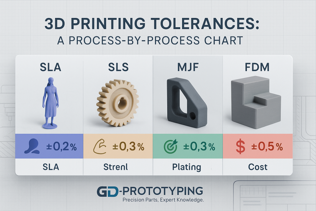
| Process | Typical Tolerance | Minimum Feature Size | Key Strengths |
| SLA (Stereolithography) | ±0.2% (lower limit of ±0.1 mm) | 0.2 mm | Excellent detail, smooth finish. |
| SLS (Selective Laser Sintering) | ±0.3% (lower limit of ±0.3 mm) | 0.8 mm | Strong functional parts, no supports. |
| MJF (Multi Jet Fusion) | ±0.3% (lower limit of ±0.3 mm) | 0.6 mm | Fast production, good strength. |
| FDM (Fused Deposition Modeling) | ±0.5% (lower limit of ±0.5 mm) | 1.0 mm | Low cost, wide material range. |
A Detailed Look at Tolerances by Process
To make an informed decision, it is essential to understand why each process has the tolerances that it does. The underlying technology dictates the final outcome.
FDM (Fused Deposition Modeling) Tolerances
FDM builds parts by extruding a heated filament of plastic through a nozzle. It is the most accessible and often the most affordable 3D printing technology.
- Why the Tolerances are Looser: The accuracy of FDM is fundamentally limited by the diameter of the extrusion nozzle, which is relatively large (typically 0.4 mm). This makes it difficult to produce very fine features. The process is also highly susceptible to thermal shrinkage and warping, as the extruded layers cool and contract. The mechanical nature of the process can also lead to slight layer shifting. For these reasons, FDM has the loosest tolerances of the common industrial processes. This is a key trade-off when comparing Resin vs FDM.
- Typical Value: ±0.5% (with a lower limit of ±0.5 mm).
SLA (Stereolithography) Tolerances
SLA builds parts by using a UV laser to cure a liquid photopolymer resin. It is renowned for its precision and ability to produce fine details.
- Why the Tolerances are Tighter: The accuracy of SLA comes from the extremely small spot size of the laser beam, which can be as fine as 0.025 mm. This allows the process to draw incredibly fine and precise features. Additionally, SLA is a low-force process that operates at or near room temperature, which significantly reduces the thermal stress and warping seen in other technologies. The result is one of the most accurate and repeatable 3D printing processes available.
- Typical Value: ±0.2% (with a lower limit of ±0.1 mm).
SLS (Selective Laser Sintering) Tolerances
SLS builds parts by using a CO₂ laser to sinter a bed of nylon powder. It is a workhorse for producing durable, functional parts.
- Why the Tolerances are Moderate: The accuracy of SLS is quite good, but it is primarily limited by thermal effects. The entire powder bed is heated to a high temperature, and the parts then cool down slowly over many hours. This large thermal change can lead to some predictable shrinkage and a low risk of warping, which is accounted for in the printing process. The laser spot size is also larger than in SLA, which limits the minimum feature size.
- Typical Value: ±0.3% (with a lower limit of ±0.3 mm).
MJF (Multi Jet Fusion) Tolerances
MJF also builds parts from a bed of nylon powder but uses a different fusion method involving an inkjet array and an infrared lamp.
- Why the Tolerances are Moderate and Consistent: MJF's tolerances are very similar to SLS, as they are both governed by the thermal shrinkage of a large powder mass. However, MJF's layer-wise fusion process, controlled by a precise detailing agent, can lead to slightly more consistent and repeatable results across a build platform. This makes it an extremely reliable technology for producing series of identical parts.
- Typical Value: ±0.3% (with a lower limit of ±0.3 mm).
For a deeper technical dive into the three key industrial processes discussed above, see our comprehensive SLA vs SLS vs MJF guide.
Design for Manufacturability: How to Improve Part Accuracy
Engineers are not just passive recipients of a process's inherent tolerance. They can actively design parts in a way that maximizes their potential for accuracy.
How Can Engineers Design for Tighter Tolerances?
- Add Fillets and Radii: Sharp internal corners act as stress concentrators and are prone to warping. Adding a small fillet or radius to these corners helps to distribute stress more evenly, leading to a more dimensionally stable part.
- Avoid Large, Flat, Unsupported Surfaces: A large, thin, flat surface is the most likely geometry to warp during printing and cooling. Adding integrated ribs or gussets to the design can significantly increase the stiffness of the surface and prevent this distortion.
- Design with Uniform Wall Thicknesses: Parts with both very thick and very thin sections will cool at different rates. This can create internal stresses that pull the part out of shape. Designing with a consistent wall thickness throughout the part promotes uniform cooling and better accuracy.
- Orient Critical Features Correctly: If a part has a hole that requires a very tight tolerance, it is best to orient that feature parallel to the build platform (in the XY plane). Features printed in this orientation are generally more accurate and have a better surface finish than those built vertically (in the Z direction).
- Specify Critical Tolerances Only Where Needed: Applying a very tight tolerance across an entire part can make it unnecessarily expensive or difficult to produce. Use title block tolerances for non-critical features, and only specify tight tolerances on the specific features that absolutely require them, such as mating surfaces or bearing bores.
Conclusion
Understanding the realistic dimensional tolerances of each 3D printing process is essential for successful product development. It allows engineers to design parts that will fit, function, and perform as intended. The choice of technology has a direct and predictable impact on the final accuracy of a component. SLA leads for ultimate precision, while SLS and MJF offer excellent accuracy for strong, functional parts, and FDM provides an economical option for less critical prototypes.
By designing for manufacturability and partnering with an expert service provider, you can ensure your 3D printed parts meet your specifications every time. At GD-Prototyping, our team has the deep process knowledge required to deliver high-quality, dimensionally accurate parts across all major additive manufacturing technologies.